![]()
![]()
![]()
![]()
![]()
![]()
![]()
![]()
![]()


All my content and ptohos

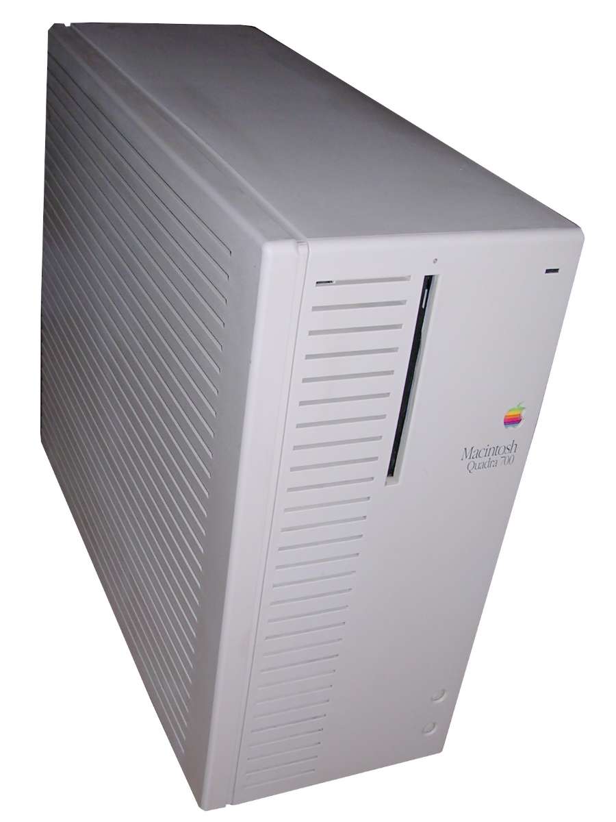
Macintosh Quadra 700
Quadra 700, releasd in 1991, was one of these faster
Macs targeted to high-end market. The unit has, as most Quadras,
Motorola 68040 processor with a full FPU included. By default, 4MB of
RAM was build into mainboard and more could be installed using 30-pin
RAM modules in 4 slots (usually, 8MB or 20MB configurations were used).
Hard drives were up to choice - from 80MB for simple office work (but
who bought Quadra 700 for office work?), a typical configuration with
160MB drive, up to high-end configuration with 400MB SCSI drive (made by
Seagate), totally sufficient for databases and image processing. The
average drive in 1991 was around 100MB, and in some applications even
20-40MB. There also was a drive-less version which, probably, was
planned as network station.
With Quadra 700, Apple started a new trend in which a higher-end
computers had tower cases while low-end got desktops, LCs even smaller
"pizza box" casings. This particular casing was based on a desktop
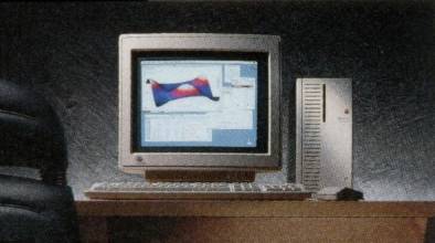
Macintosh IIci with modified front. The computer got some popularity
especially in desktop publishing where its significant power was used
for image processing. For larger video needs, it was possible to expand
video memory using special SIMMs.
| Model No: | M5920 |
|
| Year: | 1992 | |
| Discontinued: | 1994 | |
| CPU: | Motorola 68040 25MHz | |
| RAM: | 20MB (16+4MB on board) | |
| Max. RAM: | 64MB (68 visible?) | |
| RAM Type: | 4x30-pin SIMM | |
| Hard disk: | 250MB SCSI, 3.5" SL (originally 400MB) Also delivered with 80MB, 160MB, diskless. |
|
| Floppy drives: | 1 1.4M 3.5" Some disk-less versions BTO |
|
| Other drives: | - | |
| Graphics: | 512kB - 2MB VRAM | |
| Sound: | 1-channel | |
| Display: | External, 15-pin connector | |
| Dedicated OS: | Mac System 7.1 | |
| Maximum OS: | Mac System 8.1 | |
| Expansions: |
-
ADB. - 4 SIMMs for RAM Expansion - ROM SIMM in some units - 4 VRAM SIMMs - 2 NuBus slots |
|
|
|
||
|
|
||
| Connectors: | - 15-pin video
connector - External SCSI port (DB25) - AAUI network card connector - 2 serial ports (RS-422) for modem and printer) - 2 ADB connectors for keyboard and mouse - Sound output - Microphone in |
|
My unit comes from a printing studio in which it was used with a large
printing machine made by Linotype-Hell, a German company which made such
devices. It was probably one of "Vulcan" series machines. It is also
customized specifically for use with the device by a RIP board. The RIP
(Raster Image Processor) is a specialized pricessor (here it's Intel
i960), which converted document made in some document-description
language (like PostScript or PCL) and bitmaps of different resolutions
into stream of bits representing raster made on paper by printing
machine. The interesting thing is that while the board contains own CPU
and memory, it is not connected only by NuBus slot - the slot is used
only to supply power and some control to board. The main data input is
supplied by SCSI, the board, with proper drivers, uses a fast SCSI bus
to get data. Such approach has been selected probably to minimize any
delays which could be caused by e.g. other boards and could be fatal for
constant output of bit stream for machine printing in real time.
Unfortunately, the hard disk was bad and I had to replace
it, so I have no idea how exactly the software works. The 400MB SCSI
unit (Seagate ST1480) uses 5 platters and quite oversized ceramic heads,
during start-up these heads are kept dangerously close to hub. Any small
shock before loading / after unloading when hub is spinning causes heads
to hit the spinning hub and become irreversibly damaged.
Disassembly
Remove screw on the rear, unlatch two tabs and open it towards front.
Remove cover. Now you have access to expansion boards and slots as well
as CPU with its heatsink.
The power supply unit connects to the mainboard using a transfer
connector located on its casing, not a cable.
To remove HDD, press two latches on its sled and it should be possible
to remove it. Remember about LED connector - HDD LED is in the topmost
vent hole.
To get into RAM, VRAM, battery and floppy disk drive, remove HDD and
remove one screw in the round part of drives holder. Near the side there
will be a latch - press it away from computer's side to unlock and
remove. Power supply is interlocked with the drive holder, so remove it
(it slides in two rails) together.
72-pin SIMMs are VRAM. 40-pin SIMMs are RAM.
|
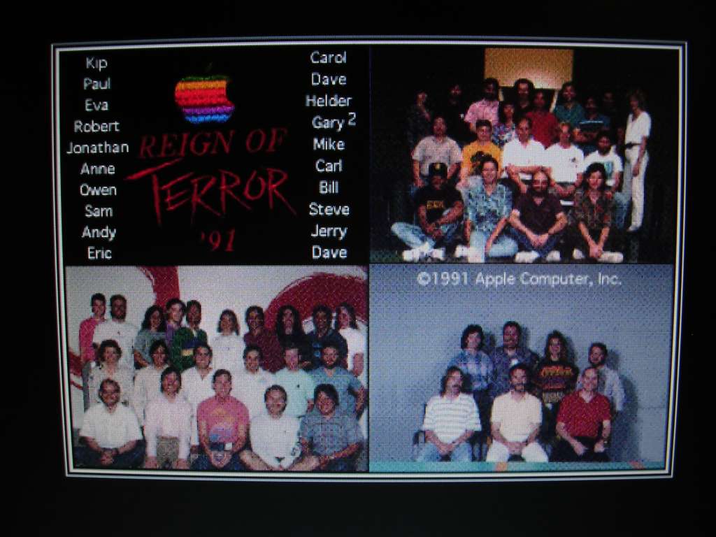
Easter egg The Easter egg from Quadra 950 works here too. To see the "Reign of Terror '91" team photo start the computer up and hold S, E, T, and Esc simulatneously. If the photo shows in black and white, you may need to change Monitor control panel (at least 256 colours). You continue to boot when you click.
|
 |
https://www.youtube.com/watch?v=c4bPIjJVh8E - Mac Quadra
advertisement featuring Quadra 700.
http://lowendmac.com/thompson/06/0512.html - Someone made a
multimedia system of LC Mac. Not Quadra 700, but similar.
https://archive.org/details/TNM_Macintosh_Quadra_Sales_Brochure_from_Apple_Computer/page/n1
- Quadra sales brochure, information about Quadra 700 and 900/950,
photos and expansion possibilities.