![]()
![]()
![]()
![]()
![]()
![]()
![]()
![]()
![]()


All my content and ptohos

PS/2 Keyboard / Mouse adapter for Atari Mega ST
The first thing is that I'm not an Atari ST extensive user nor
fan. I recently bought an Atari ST without keyboard or mouse, so I decided to
connect a PS/2 keyboard and mouse to it (original keyboards became awfully
expensive for some unknown reason). I quickly found an
Eiffel interface, which is programmed very
well, but the microcontroller used for it is hardly accessible now. So I decided
to implement the simple part of protocol using Arduino C.
This solution is definitely not complete nor bug-free. More, I think that this
implementation has some significant bugs I have not tested because lack of
testing software, so I leave this on a GPL license. What I tested and works is:
- Keyboard - works.
- Mouse: Works in primary boot-up mode (Programmed relative)
- Joysticks - as above, work after power-up.
The Atari Mega ST Keyboard is connected to the computer using a serial port on
TTL levels, running at 7812.5bps (in fact 7812bps are in tolerance). The
microcontroller has a few functions:
- Communicates with computer using serial interface and ikbd (Intelligent
Keyboard) protocol;
- Scans and controls matrix keyboard, emitting keycodes;
- Translates X/Y mouse position to "pulses" and converts it to relative or
absolute coordinates, also in some mode to key presses;
- Monitor joystick ports for contact presses, then emits joystick command
packages or, in some modes, arrow keys. Also it can go to mode in which it
constantly monitors joystick port or fire button emitting only its state;
- Maintain a small Real time clock and calendar (non battery-backed);
- Maintain RAM R/W of microcontroller unit (not used too much);
As you can see, things are quite complicated. The protocol has a command set for
setting modes, interrogating states and return sequences. I decided to implement
the most significant parts of it using Arduino, as the C code allows to sketch ideas in quite short time.
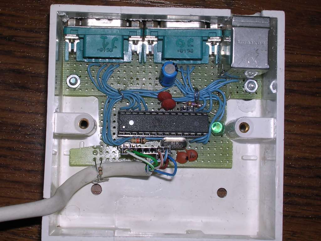
the code has been developed in about 2-3 hours, testing using Atari ST with TOS
1.x, and building a prototype on
universal PCB took 2 times more :). The schematic is following (don't take it as
100% correct, better use pin description below):
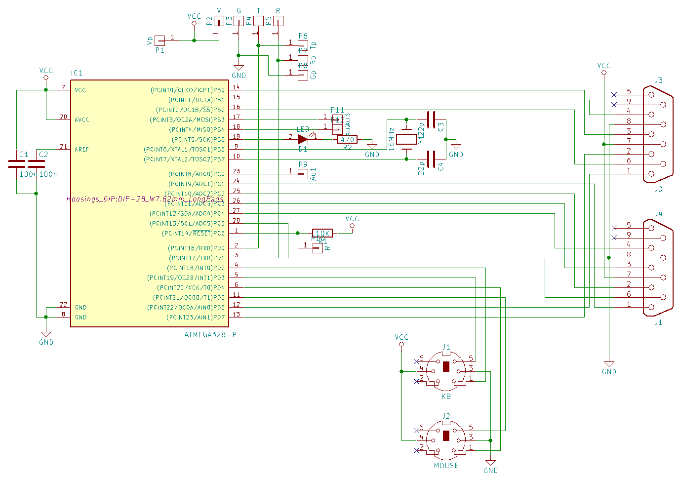
Joystick connector is just a GPIO pins. Additional LED has quite limited usage
here, it was used to debug purposes. The code is made the way that it needs both
PS/2 mouse and keyboard to boot up. It has a Public domain
PS2 library for mouse
support on interrogation
and PS2Keyboard library (GPL) to use keyboard at interrupt.
The pinout of the Atari keyboard connector is following (looking into socket):
123456
-vvvvvv-
| |
| |
--|__|--
1,2 - +5V DC
3 - Tx
4 - Rx
5,6 - GND
Pinouts of PS/2 connectors and joystick connectors are following:
|
|
 |
|
| 1 - DATA 3 - GND 4 - +5V 5 - CLK |
1 - Up 2 - Down 3 - Left 4 - Right 6 - Fire 7 - +5V 8 - GND |
Joystick works by connecting a pin to GND, so input with built-in pull-up
resistor in Arduino is totally sufficient.
The Rx/Tx lines to Atari have to be crossed. For typical PC keyboard and mouse,
single wires for Vcc and GND are OK, but if something more will be connected
(like joysticks with own logic, advanced keyboards, older mice) you should think
about 2 wires as in original connector.
The pins assignment is following:
| Ard. pin | AVR pin | Target | Description |
| 0 | 2 | To Tx Atari pin | Serial line |
| 1 | 3 | To Rx Atari pin | Serial line |
| 2 | 4 | KB pin 1 | Keyboard data |
| 3 | 5 | KB pin 5 | Keyboard clock (MUST be interrupt pin!) |
| 4 | 6 | Mouse pin 5 | Mouse clock |
| 5 | 11 | Mouse pin 1 | Mouse data |
| 6 | 12 | J0 DB9 pin 1 | Joy 0 up |
| 7 | 13 | J0 DB9 pin 2 | Joy 0 down |
| 8 | 14 | J0 DB9 pin 4 | Joy 0 Right |
| 9 | 15 | J0 DB9 pin 3 | Joy 0 left |
| 10 | 16 | J0 DB9 pin 6 | Joy 0 fire |
| 11 | 17 | ----free---- | |
| 12 | 18 | ----free---- | |
| 13 | 19 | Diagnostic LED Anode | |
| A0 | 23 | ----free---- | |
| A1 | 24 | J1 DB9 pin 1 | Joy 1 up |
| A2 | 25 | J1 DB9 pin 2 | Joy 1 down |
| A3 | 26 | J1 DB9 pin 4 | Joy 1 right |
| A4 | 27 | J1 DB9 pin 3 | Joy 1 left |
| A5 | 28 | J1 DB9 pin 6 | Joy 1 fire |
Download source code of project:
|
|
MegaPS2_20180427.7z |
The code can be compiled by
Arduino IDE. To modify keyboard map, use keymap.h file
and mess there. Some codes, especially mutli-byte ones, are shifted by negative
offset to fit
everything in array under 256 bytes, there are comments in all lines in array
what value is responsible for which key.
The prototype has been developed on Arduino Uno board with ATMega328
microcontroller, and code occupies about 10kB (I think it theoretically may be
trimmed down to fit in ATMega8, but it requires some more thinking) leaving also some
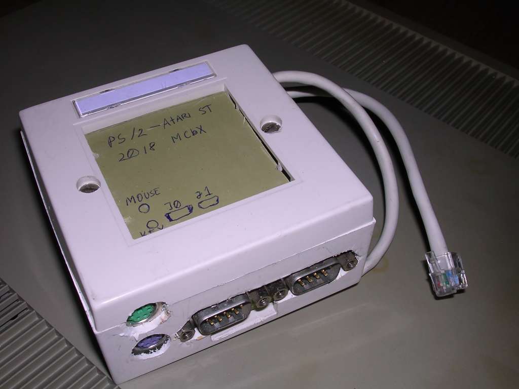
RAM free. It has been made as a device using universal PCB instead of etched
one, and put into casing made of old LAN socket.
Sources for protocol:
https://archive.org/details/Intelligent_Keyboard_ikbd_Protocol_Feb_26_1985 -
iKbd protocol specification
https://archive.org/details/Atari_ST_Internals_Abacus_2_3rd_edition_1986 - Atari
ST Internals, has some nice description of iKbd protocol.
MCbx, 2018

