![]()
![]()
![]()
![]()
![]()
![]()
![]()
![]()
![]()


All my content and ptohos

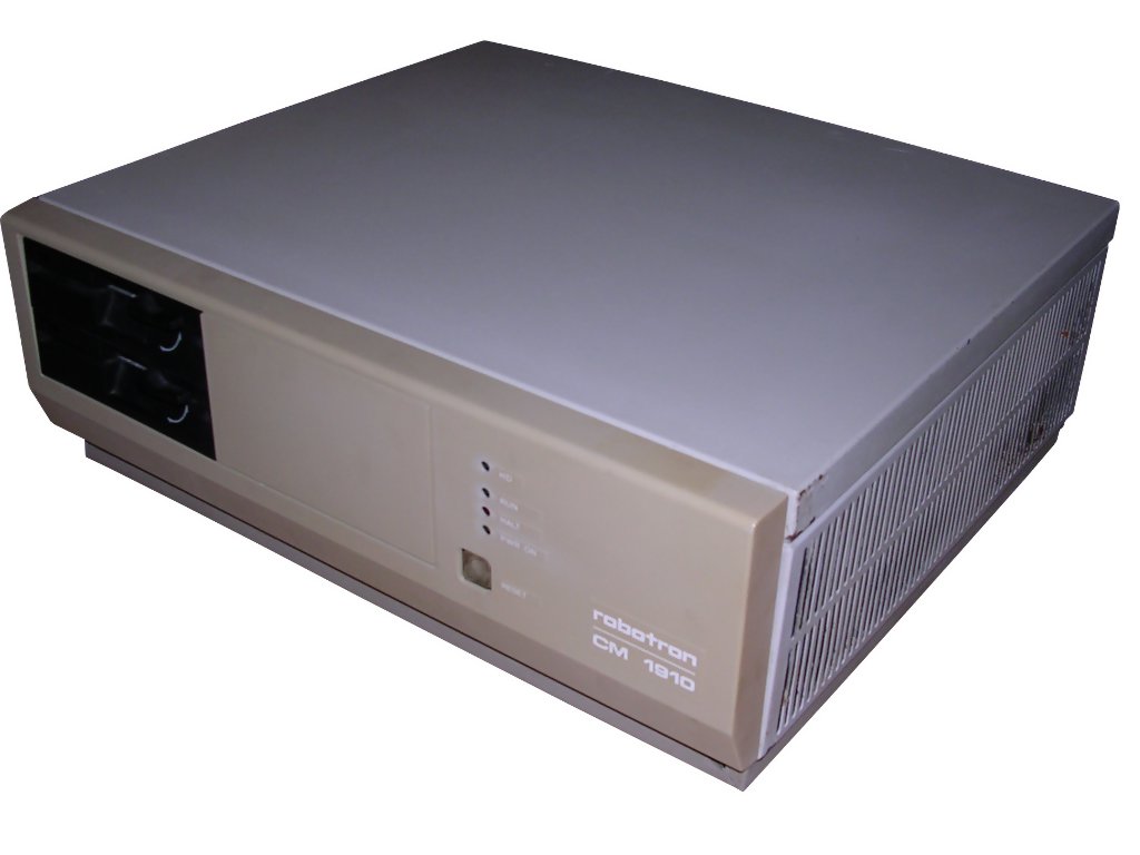
Robotron A7150 (CM1910)
In 1980s IBM PC and its clones gained popularity as
computers for business and office applications. Development of boards
for better graphics and sound made PC an universal machine for gaming,
design or even computations. In Eastern Block countries in 1980s the
most successful systems were based on mainframe or were small, usually
Z80-powered systems. But there were numerous tries to build a
PC-compatible computer and if such try succeeded, machine was
manufactured until parts were supplied (or someone seen its
inprofitability). The Robotron A7150, in Unified Notation called CM1910,
was a result of a series of computers, achieving sufficient
compatibility with IBM PC. Earlier machines of the series were not
totally PC compatible. Although A7150 was released in 1988, much after
more PC-like EC1834 from 1986, it was based on A7100, older than EC1834.
A7100 was the machine based on much older MMS-16 architecture with
Multibus bus as the main communication method.
The computer is built in 9 double-Eurocard boards, in which every board
has its own function. The Multibus rail joins the cards together. This
bus contains not only Intel 8086 buses, but also control signals for
boards cooperation. Some of these boards contain a small Z80 system!.
The graphics adapter was compatible with PC character mode graphics
card, running 80x25 mode as well as specialised 640x480 graphics mode
which these times was completely sufficient for CAD applications. The
CPU was originally a Soviet one, yet in later units it is western - made
by Siemens. My computer also contains a Siemens 8087 FPU and as the
professional machine, most A7150s contained FPU. The machine was used as
a high-end workstation for computations and design. It was possible to
hook up a few terminals and work in a cooperative system. The computer
had port to connect graphics tablet for acquiring design drawings. 512kB
of RAM, present by default in standard product, was a downfall there, so
1MB and 920kB cards were available.
As for software, there was a variety of programs: CAD software working
in graphics mode, DOS analog ( calledDCP1700), CP/M-86 analog (called
CP/K) or even MS Windows 3.0 variant with drivers allowing to run on
640x480 graphics. It was also possible to run MUTOS1700 which was
UNIX-like system.
| Manufacturer | VEB Robotron-Elektronik Dresden |
|
| Origin | East Germany | |
| Year of unit | 1988 | |
| Year of introduction | 1988 | |
| Class | XT | |
| CPU | 8086+87 | |
| Speed | 5MHz | |
| RAM | 512kB | |
| ROM | BIOS, ACT, Monitor | |
| Graphics | Proprietary, 640x480 max | |
| Sound | PC Speaker | |
| System expansion bus | Multibus | |
| Floppy/removable media drives | 2x 720kB 5.25" FDD (Quad-density) |
|
|
|
||
|
|
||
| Hard disk: | 1x 20MB MFM "Winchester" hard drive |
|
|
|
||
|
Peripherals in collection: |
||
| Other cards:
|
- | |
| Non-standard expansions: | ... all cards? | |
| Operating system(s): | DCP1700, CP/K, MUTOS |
My unit starts and boots up well, yet I have no keyboard for it, so it doesn't pass the POST, here known as ACT. ACT is a quite complex piece of software built in ROM, which can check proper system operation, boot the proper drive or, in case of error, jump to CPU's monitor also stored in ROM.
The keyboard is made around dedicated Z80-like microcontroller.
This construction is definitely not a standard one, yet it has
capabilities similar to early PCs: Two 360K floppy disk drives, two MFM
hard disks (but in most units parts for second one are not installed),
good resolution video card. The difference is in power consumption
(original IBM PC used much less power than Robotron's machine) and in
expandability - CM1910 cannot be easily expanded with specialised
boards.
Robotron A7100
In 1980s IBM PC and its clones gained popularity as
computers for business and office applications. Development of boards
for better graphics and sound made PC an universal machine for gaming,
design or even computations. In Eastern Block countries in 1980s the
most successful systems were based on mainframe or were small, usually
Z80-powered systems. But there were numerous tries to build a
PC-compatible computer and if such try succeeded, machine was
manufactured until parts were supplied (or someone seen its
inprofitability).
Robotron A7100 was the first widely-produced 16-bit computer in German
Democratic Republic. It was derived from MMS16 16-bit system, which fit
on double-Eurocard boards, so in quite modern-looking case there are 8
or 9 boards connected by backplane. Although similar to PC, it is not
compatible with PC as it has different memory map, with place for
graphics board compatible with some early graphics extensions.
However, after it was released, a software PC emulator has been
developed. It was found that it is relatively easy to switch it to be
totally PC-compatible, so later A7150 was PC-compatible.
An interesting thing is about processors. In all marketing leaflets
there is information that processor was Soviet equivalent of 8086. But
most A7100 and A7150 units have Siemens 8086, imported from West
Germany. Marking eastern CPU in materials allowed Robotron companies to
import components not accessible in western markets from Soviet Union
easier. Although it was not officially possible to import computer parts
by socialist-block country, it was done unofficial ways and Robotron
made printers for West Germany (Prasident, Cellatron, some Commodore
mechanisms) too.
| Manufacturer | VEB Robotron-Elektronik Dresden |
|
| Origin | East Germany | |
| Year of unit | 1987 | |
| Year of introduction | 1986 | |
| Class | XT | |
| CPU | 8086 (Mf. by Siemens) |
|
| Speed | 5MHz | |
| RAM | 512kB (2x256kB on 2 boards) |
|
| ROM | BIOS, ACT, Monitor | |
| Graphics | Proprietary, 640x400 4-shade grayscale |
|
| Sound | PC Speaker | |
| System expansion bus | Multibus | |
| Floppy/removable media drives | 2x 720kB 5.25" FDD
(Quad-density) |
|
|
|
||
|
|
||
| Hard disk: | None |
|
|
|
||
|
Peripherals in collection: |
||
| Other cards:
|
- | |
| Non-standard expansions: | ... all cards? | |
| Operating system(s): | DCP1700, CP/K, MUTOS |
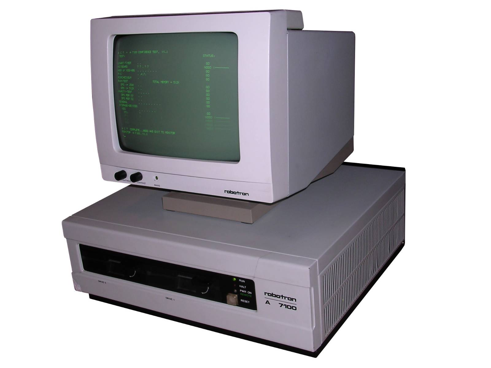
My unit starts and boots up well, it was restored to working condition. I have no keyboard for it, so it doesn't pass the POST, here known as ACT and jumps to monitor. The only thing worth noting here is that the monitor's brightness and contrast knobs for K7229.24 increase in opposite directions.
ABBREVIATIONS:
- ZRE, ZVE - Processor board
- OPS - RAM (as OPeration Memory), 256kB board
- ABG - Video card. This one speaks to monitor and drives pixels to their
proper positions.
- KGS - Graphics terminal card. It's resopnsible of communicating with
keyboard, tablet and diagnostic system..
- ABS - Text mode card - this one offers 80x25 text mode and nothing else.
Exists in units without graphic mode.
- AFS - Floppy drive controller board
- KES - External drives controller, bridge between FDD/HDD/Streamer
controllers and CPU.
- ASP - Serial and parallel ports board
- AFP - Hard disk controller board
All boards have typical in east German hardware Kxxxx.y designations, e.g.: K2771.30 ZRE is CPU board of A7150.
| Contents: | Starting | Troubleshooting | Board scans | Pinouts | Links |
Starting
Forgive errors, I don't speak German at all, tried to
translate service manual.
The first thing you should see is graphics card throwing all characters
in one place. It's normal ABG board test routine after power-on. It is
not dependent on any other parts. It sometimes happens spontanically,
e.g. during codepage or keyboard set manipulations, the graphics card
sometimes just needs to reset itself. You should hear a beep from
computer and a beep from keyboard. Sometimes few very quick beeps from
keyboard, sounds like one beep. In A7100, the screen may go a bit darker
when power is applied.
Firmware may beep and alarm with LEDs.
In general:
- RUN led on and continuous sound - memory error, module missing, 400h,
401h inaccessible
- RUN/HALT blinking ~10Hz, continuous sound - ACT cannot address memory
(0..0FFFh)
- RUN/HALT blinking ~3Hz, no sound - ZVE/OPS/ZPS module clock error
- RUN/HALT blinking ~1Hz
- And 1 short beep - Error in IBF, whatever it is...
- And 2 short beeps - Interface error (ABS K7071) or EPROM error
- And 3 short beeps - IBF/Data error (ABS K7071) or VRAM / EPROM error
(if KGS/ABG module used)
After some time cursor should be visible. If it hangs on cursor, try
pressing Reset, it'll go to ACT. Information below are for A7150.
Normally, after short beep ACT should come to screen. ACT - A7150
Confidence Test, is a complex Power-On Self Test. Each test is
summarized by set of characters, such as:
TEST: STATUS
USART/TIMER: . . GO
GRAPHICS: . . . . . . . . GO
KEYBOARD: . . . . . GO
PIC: . . . . GO
...
Error is indicated by "?" instead of a dot. Like:
GRAPHICS: . . ? . . . . . NOGO
indicates error 3 in graphics, this condition prevents
booting OS (NOGO). Some NOGO situations may lead to stopping, some to
running Monitor program.
There is one more status: NOT READY, it's for floppy drives.
PIC test may be indicated by:
PIC: . .*.!. GO
It is normal, some tests may be performed this way. If
it hangs you can try to recover it with Break key.
After ACT you'll get to monitor or:
A C T SUCCESSFUL...NOW BOOTING SYSTEM
There are keyboard commands that can be used in ACT.
These are Break key (at the beginning ?disables memory counting?), A, C,
T and B. These 4 letters can be keyed in 6 seconds after third PIC test
dot appears. These commands, described as "Abort, Complete, Test, Boot"
can in most frequent cases be used to replace test or enter monitor.
Here are all errors described:
USART/TIMER:
1 - ZVE K2771.30 error in status register of KR580WW51A chip
2 - ZVE K2771.30 error in timer 2 (KR580WI53)
ABS / KGS/ABG color graphics card (OPTIONAL!)
1 - ABS/ABG internal error??
2 - ABS/KGS EPROM error
3 - ABS/KGS internal error??
4 - Interface data error??
5 - ERR status bad
6 - INT status bad
7 - IDF status bad
8 - OBF statuf bad
Errors in 5-8 may be caused by any of devices working with this signal:
ADS, ABG, KGS, ZVE.
GRAPHICS:
1 - Keyboard error (is it connected?)
2 - Keyboard not available
3 - Internal ABG/KGS error ?
4 - KGS EPROM error
5 - ERR status bad
6 - INT status bad
7 - IDF status bad
8 - OBF statuf bad
Errors in 5-8 may be caused by any of devices working with this signal:
ADS, ABG, KGS, ZVE.
KEYBOARD:
1 - Keyboard self-test error
2 - Unknown keyboard type
3 - Output buffer of USART is busy (ZVE fault)
4 - Input buffer of USART always empty.
5 - Strange answer from keyboard's microprocessor.
6 - Keyboard self-test given bad/no answer (may be keyboard or KGS
problem)
PIC:
1 - Timer 2(KR580WI53) not working properly (ZVE fault)
2 - INT status fault (ADS/ABG, KGS and ZVE use this line)
3 - Interrupt 7 expected, not happened (interrupt marked by #) (ZVE
fault)
4 - Interrupt 6 (keyboard) does not go (ZVE error)
ROMCHECKSUM:
1 - Checksum bad. How about ROMs in ZVE?
RAM TEST TOTAL MEMORY = xxx K
RAM-STATUS:
1 - Error in 0..128K
2 - Error in 128..256K
3 - Error in 256..384K
4 - Error in 384..512K
5 - Error in 512..640K
6 - Error in 640..768K
7 - Error in 768..896K
8 - Error in 896..992K
VIDEO=128K (or VIDEO=32K)
STORAGE-DEVICES:
KES:
1 - KES doesn't reset nor respond.
2 - KES EPROM fault
3 - KES SRAM error
4 - KES CTC fault
5 - KES DMA fault
6 - KES Interrupt (5) fault (ZVE may have problem getting it)
7 - KES<->RAM data errors. KES or RAM bad.
:F0: or :F1: or :F2: or :F3:
1 - FDD or FDD controller error. Is diskette good? Is drive good? AFS?
KES? FDD controller board?
:W0:
1 - HDD not identified - Disk incompatible, e.g. not LLF'ed.
2 - HDD read fault - Is HDD good?
3 - HDD calibration fault - check HDD and AFP (HDD controller) board.
Troubleshooting
The electronics in this computer rarely fails as it's quite solid although it looks cheaper than in earlier PCs (e.g. no IC sockets). The most frequently failing parts are mechanical connectors, they should be kept clean and fitted well. Ribbon cable and edge connectors for FDDs are culprit of many problems with floppy disk drives.
The most frequently failing thing is the power supply unit. Let's look at its block diagram, it's from A7150 manual but it is similar in A7100:
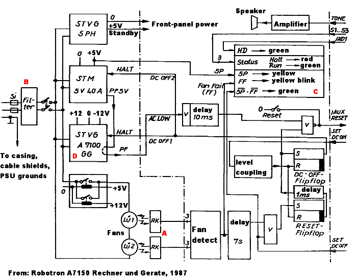
Power supply unit
The device has a large, switching power supply unit. There is also a
small, transformer-based power unit (STVG 5PH) for keeping diagnostic and power-on
systems alive as well as for potential starting up remotely by network. The main PSU consists of two high-power blocks
(STM 5V for 5V, STVG A7100 for +/-12V) which
supply +5 and +12V, as well as low-current negative voltage directly to
the bus. If the 5V block fails to deliver power, 12V supply will not
start (PF - Power Fail signal) and diagnostic systems will react by
beep. If 12V block fails to start, the system will try to run, but will
fail without picture being held at permanent RESET to minimize damage.
The blocks have totally ca. 500W, which is sufficient for a PC made of
TTL chips. They are cooled with two 220V fans, both of them are switched
on by relays when power block outputs power. Fans have optical
reflective sensors (RK) to monitor accidents in which fan stops. If fan
stops for more than 7 seconds, the
PC is turned off and green or yellow LED blinks indicating fan error (FF
- Fan Fail).
There is also a small board with PC Speaker, reset switch and state
LEDs. It is connected with a ribbon cable to the rear service connector
on CPU board to supply connections for PC speaker, reset, power on/of
and "power good" signals as well as to the switchboard for signals
coming from system bus and fans.
Another two connectors are for keyboard and graphics tablet. They are
conveniently located on the side of the computer, inside being an
extension cables. On the other side of their wires, they are connected
to boards on the rear. That's why this computer requires 3 cables
connected on the rear: Two for keyboard and tablet, one for control
panel. Power for keyboard and tablet are supplied through fuses located
in the front side near standby power supply unit.
Typical problems there are marked with red letters in
picture above:
- A - fan's optical barriers obstructed by dust. Computer turns off
after ca. 7s from turning on. Clean the barriers and fan's rotating
"mirror" stickers. Check dust filter near FDDs - fans pull the air
through a whole computer and blow it through power supply units. Filters
are in air inlet, they look like mesh of plastic threads. Rear fan is
not easy to remove, better remove boards and look through their tracks,
maybe there will be access to sensor.
- B - Filter capacitor - if computer is turned off by switch and it blows
its fuse when connected to power, filter capacitor is bad. It can be
removed and its power lines may be even connected (blue-blue,
white-white), it will work.
- C - Capacitors on front panel board - if computer doesn't start for the
first time, but after powering off and then on it boots, look for bad
electrolytic capacitors. Start checking from front panel board, then
power blocks, then PCBs with electronics.
- D - 12V power block. It heats up much. Check its capacitor. In my unit,
the keying transistor just blown by itself - which resulted in blown
fuses in PSU block, but not in computer. Transistor may be replaced by
other switching 100V, 10A NPN power BJT-transistor.
To remove power block:
- Open casing
- Remove bottom screws holding block in place. Block should start to move
back and forth.
- Slide the block off, it should go about 1-2 cm. By this, you unlink a
small signal connector near bottom.
- Remove DC connections from screw terminals. Remember which wire goes
where.
- Remove high-voltage AC connection from terminals of HV switchboard (part
covered by piece of laminate). It will not go through hole with metal
part, you have to slightly bend it and remove cable shielding from metal
clip.
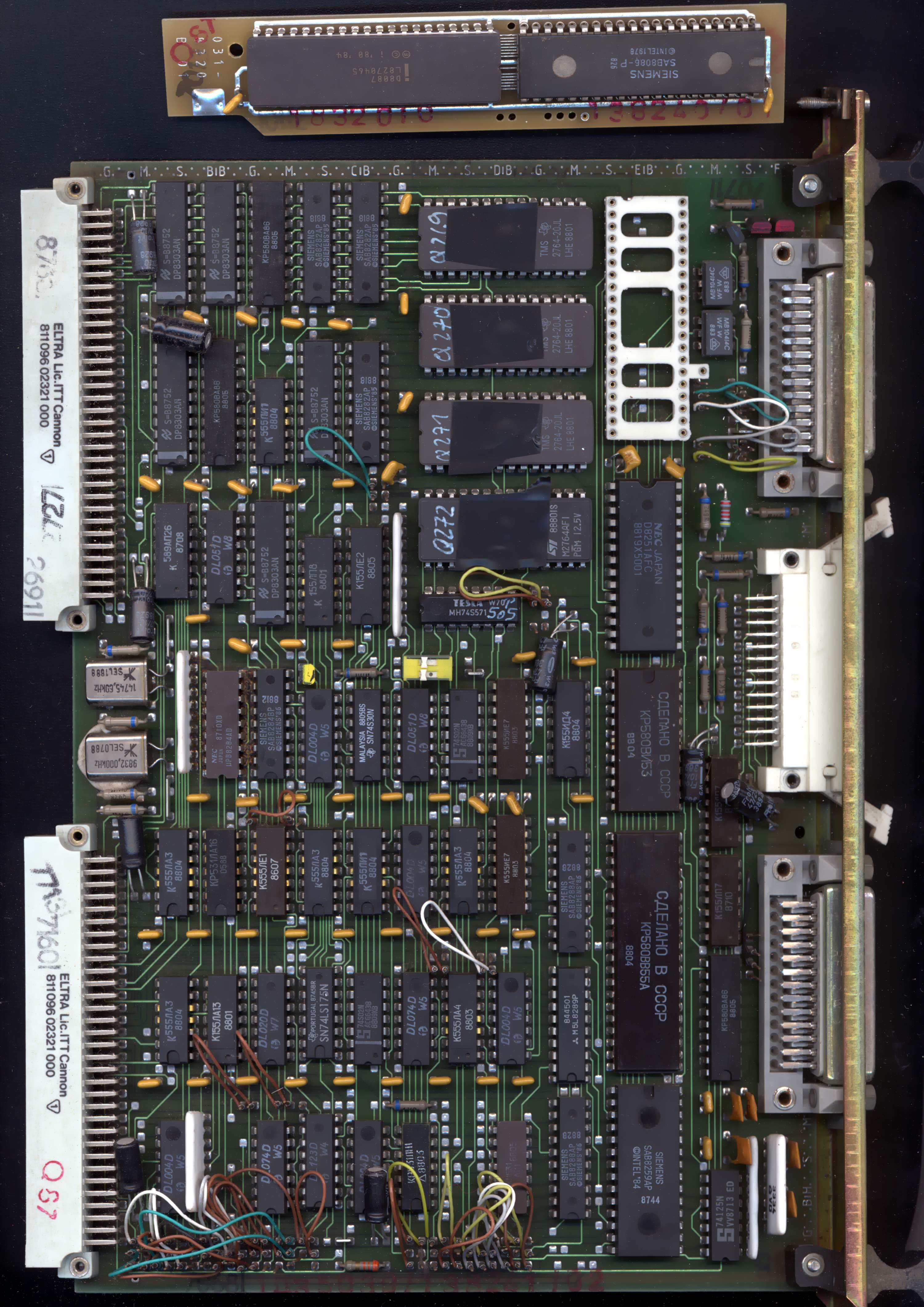
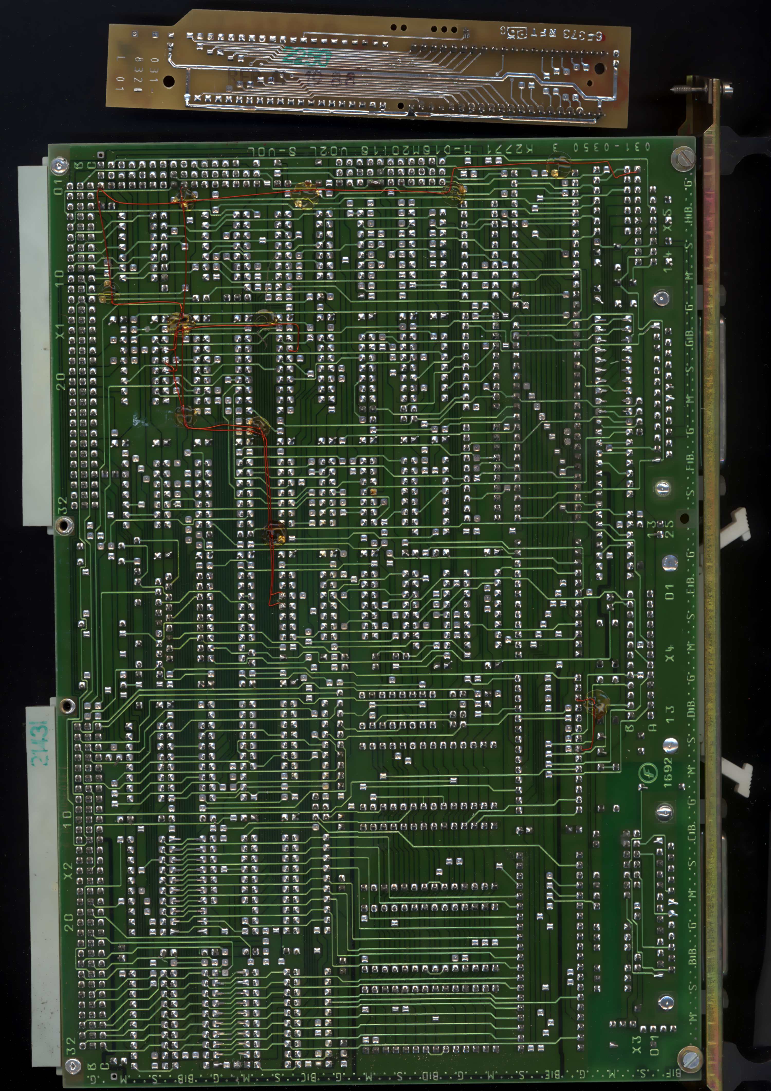
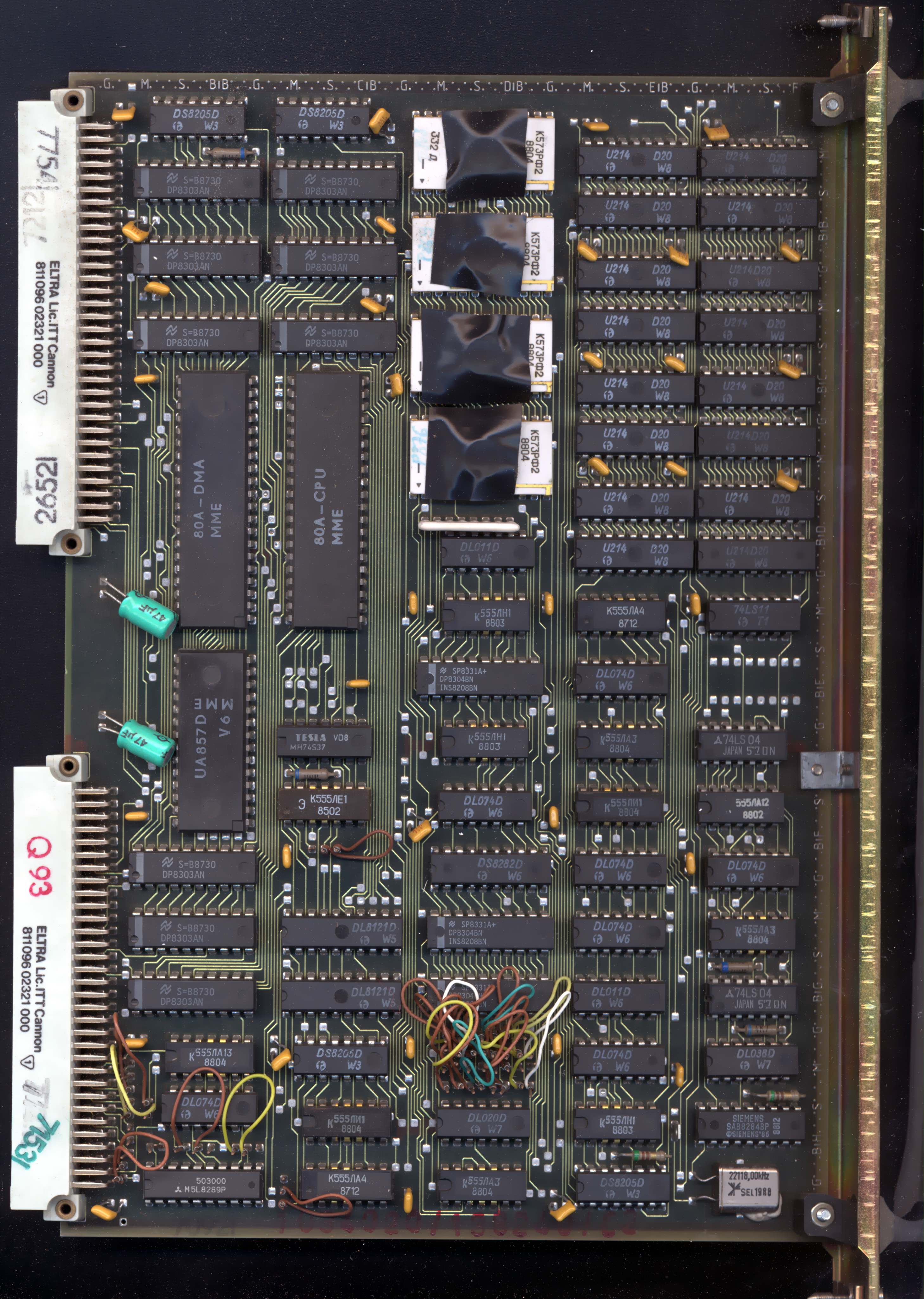
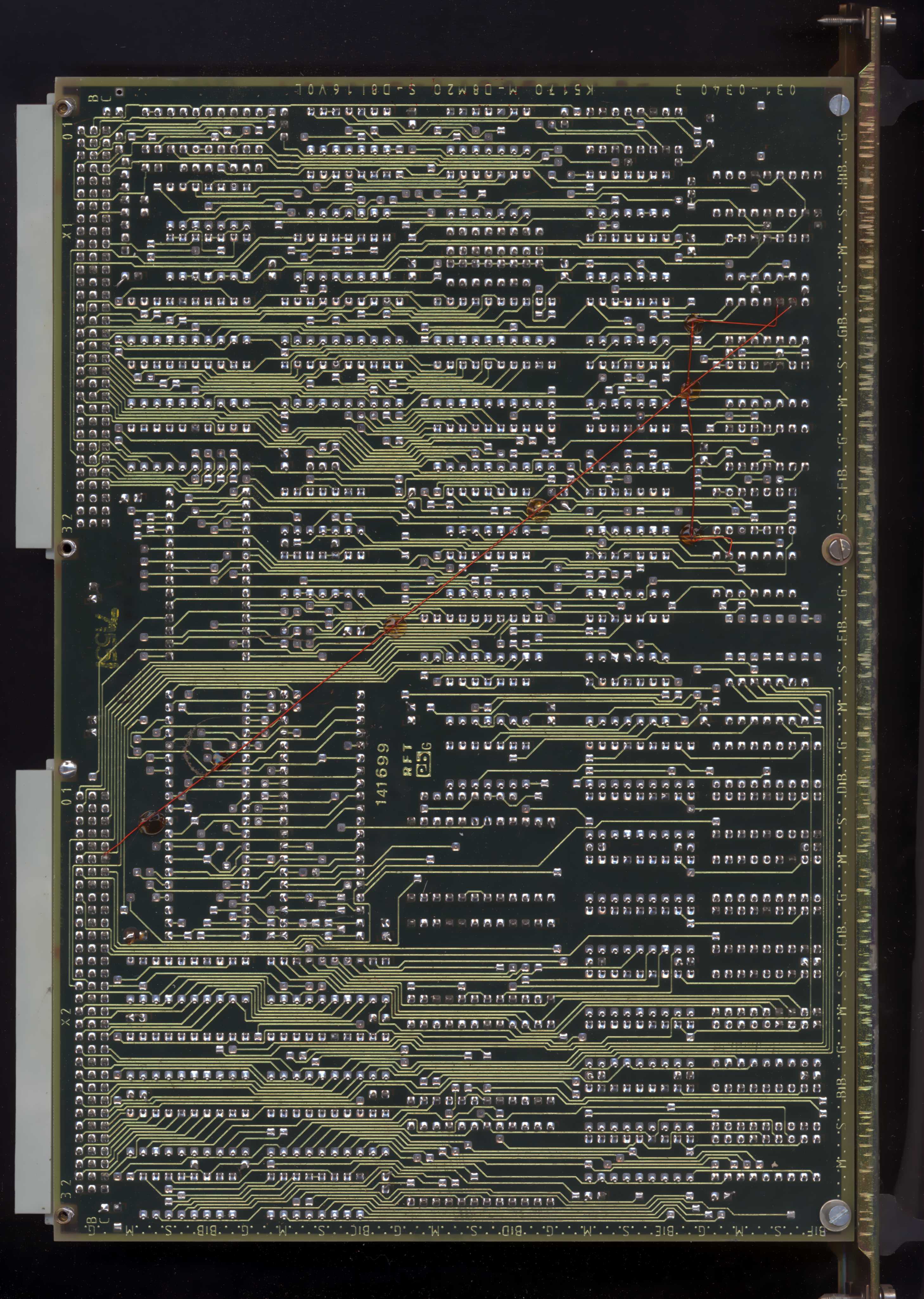
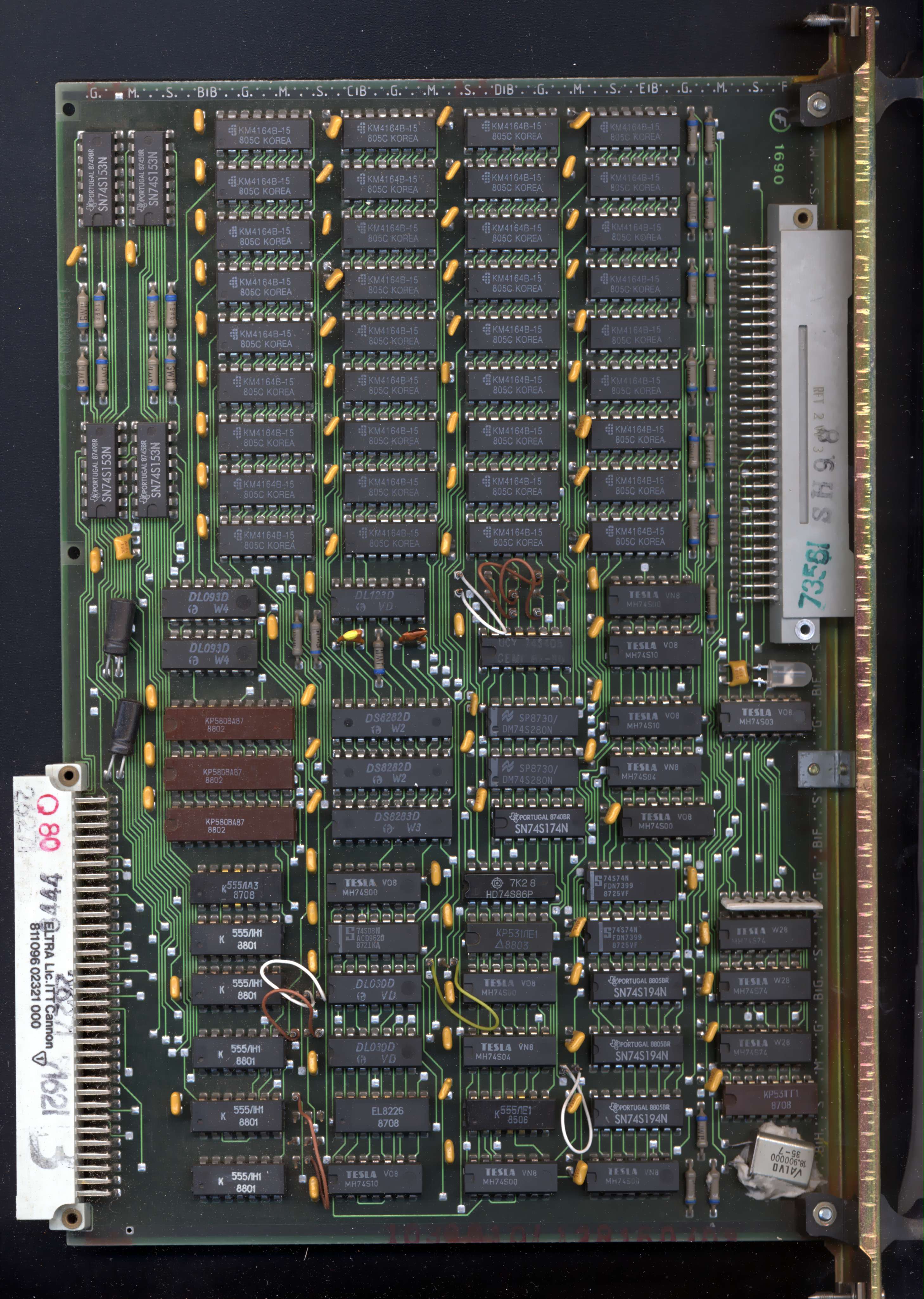
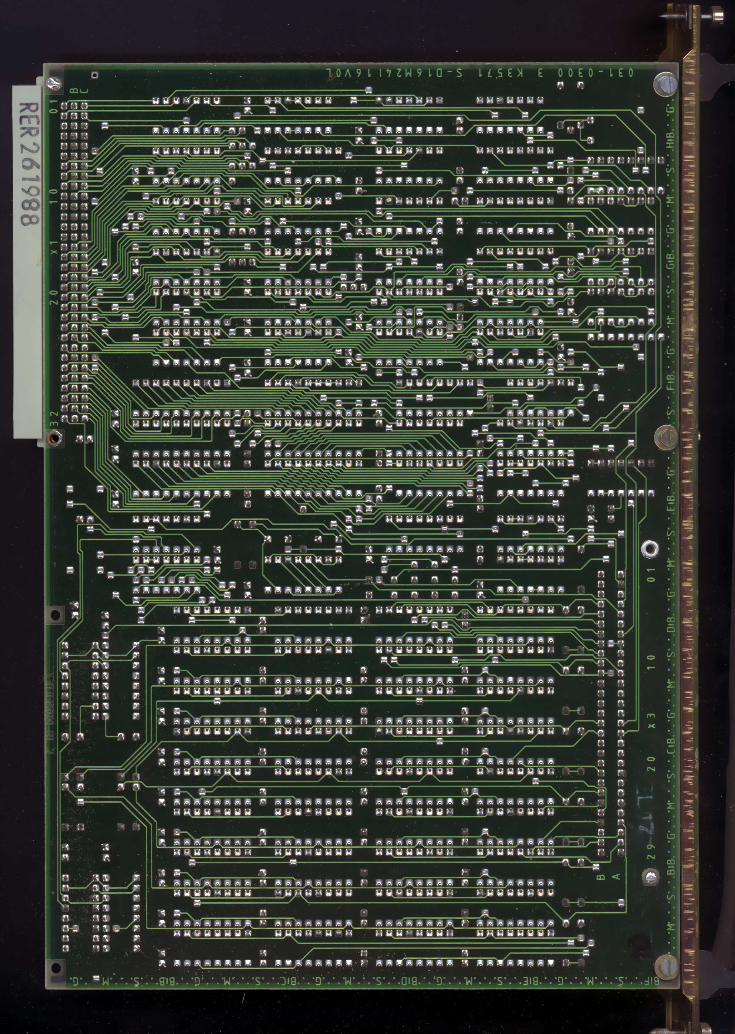
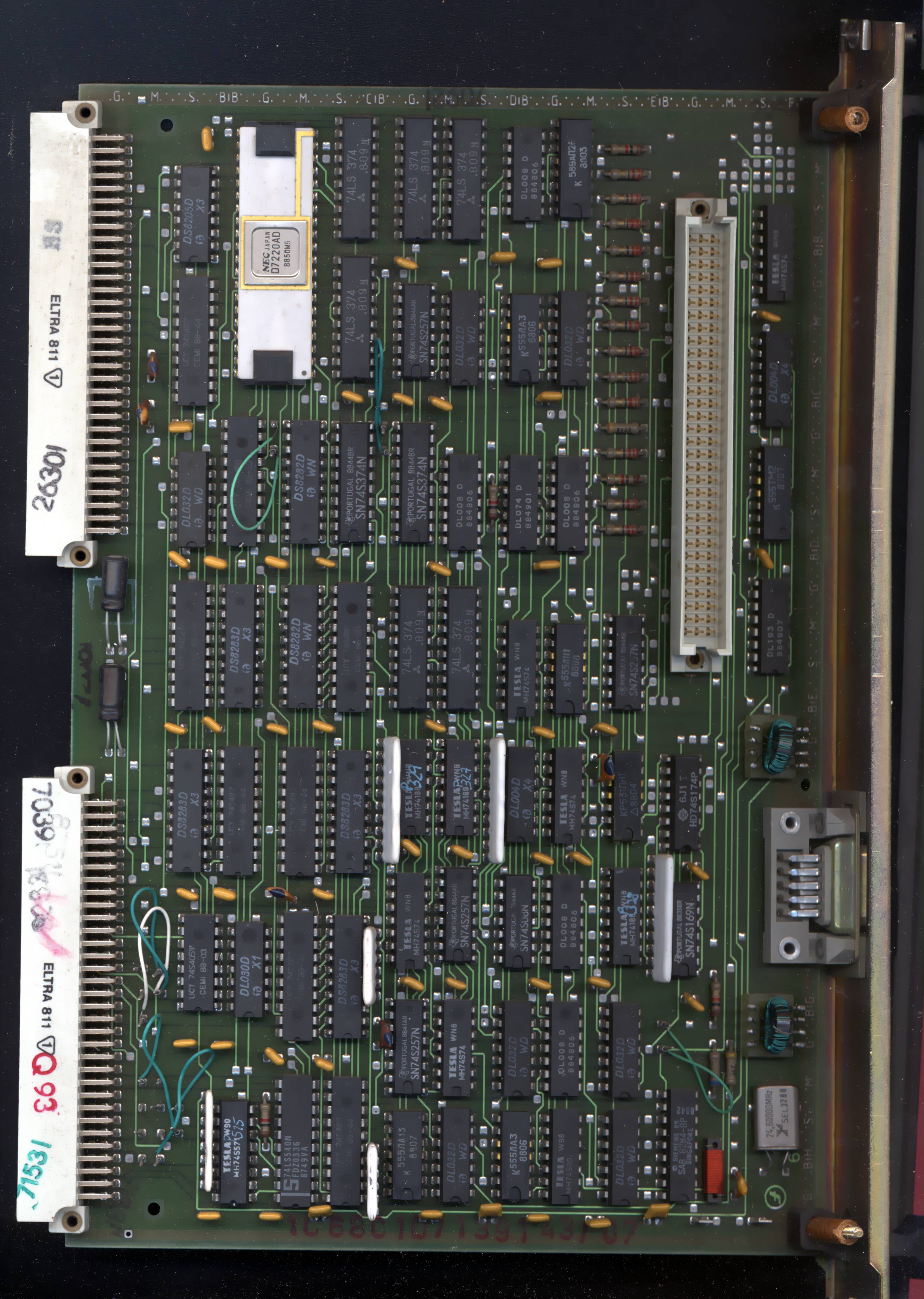
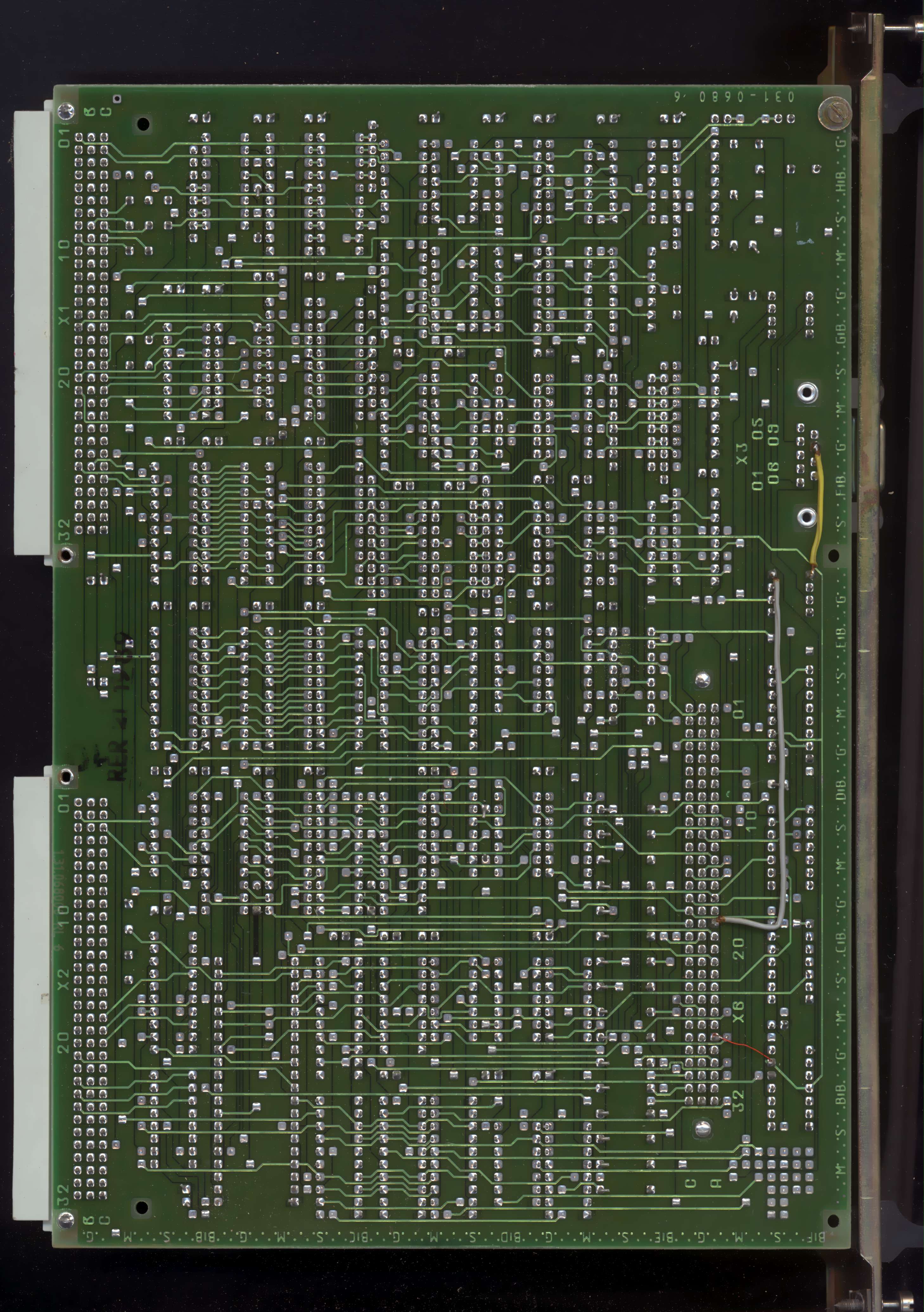
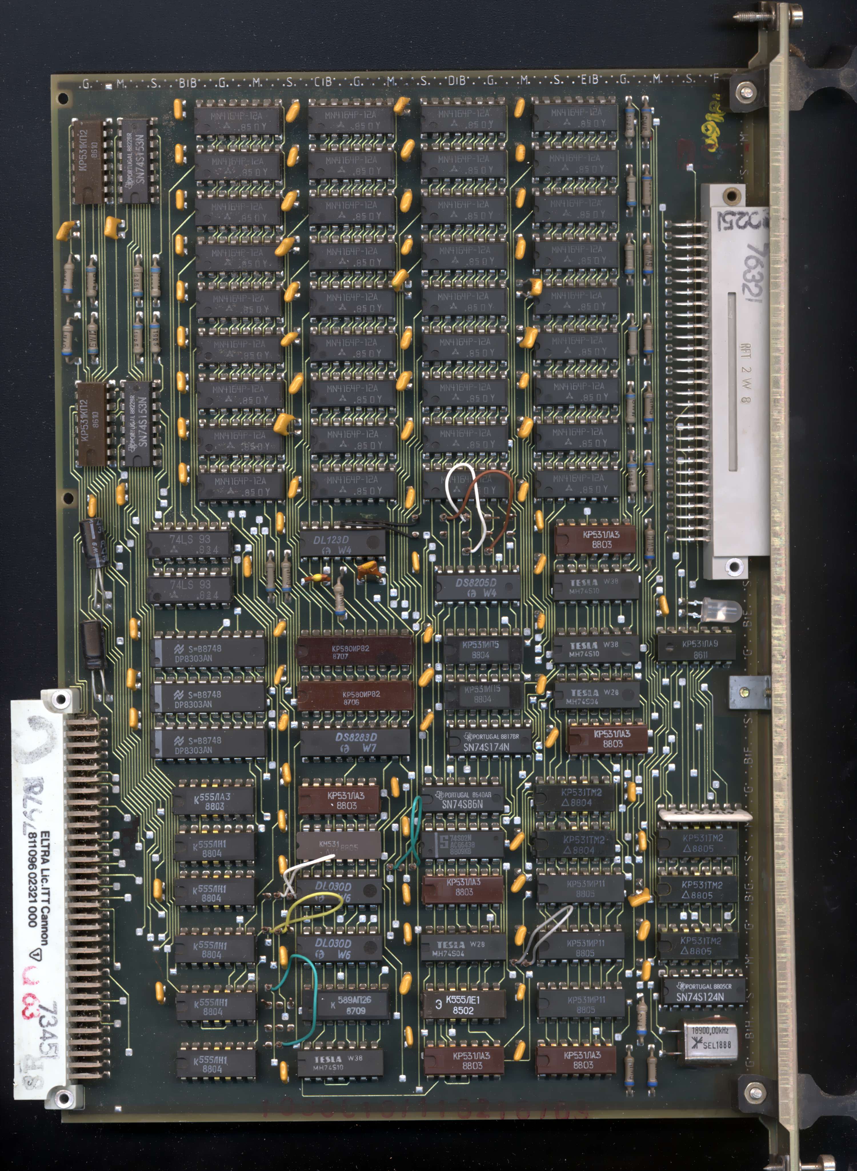
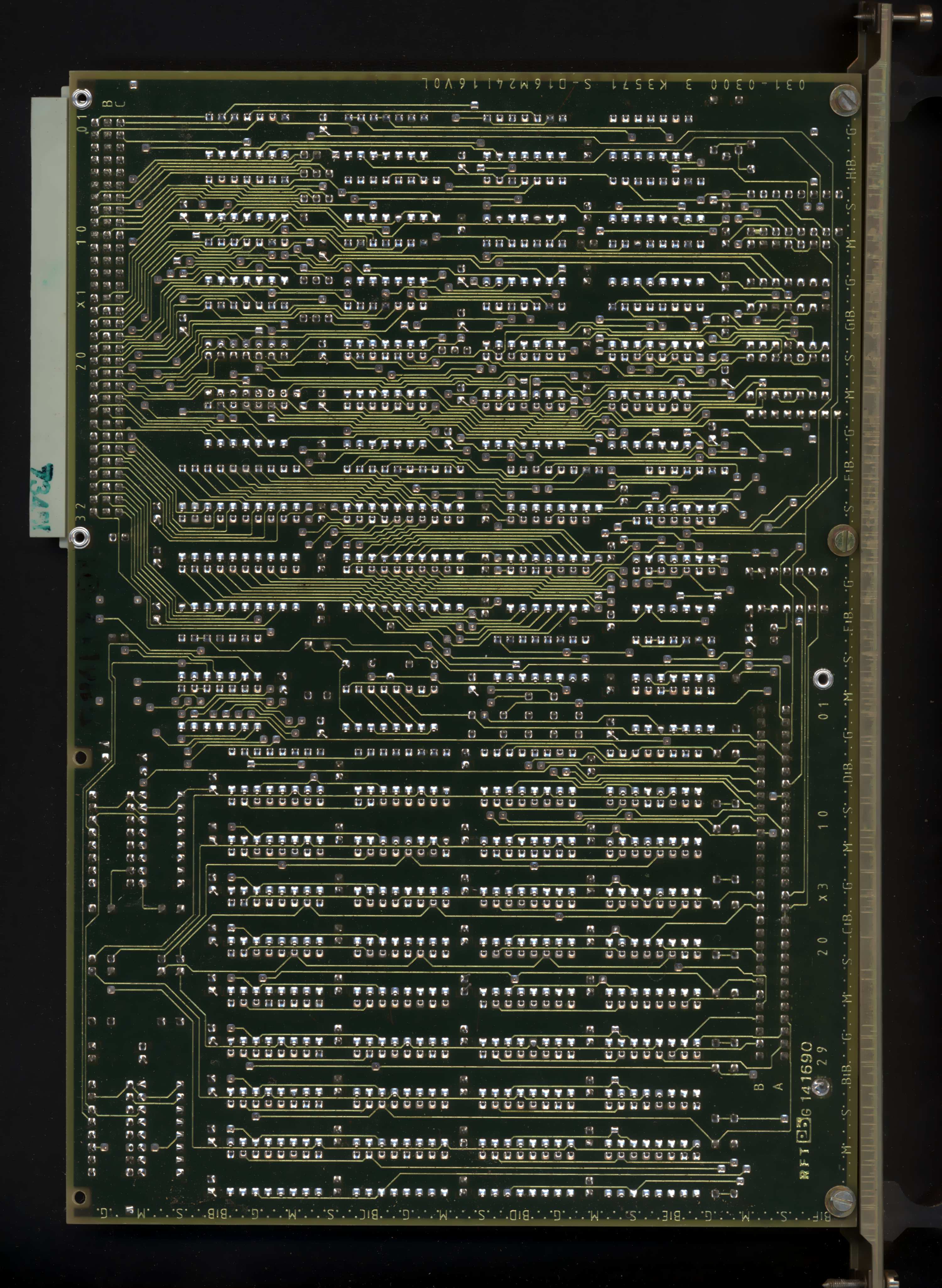
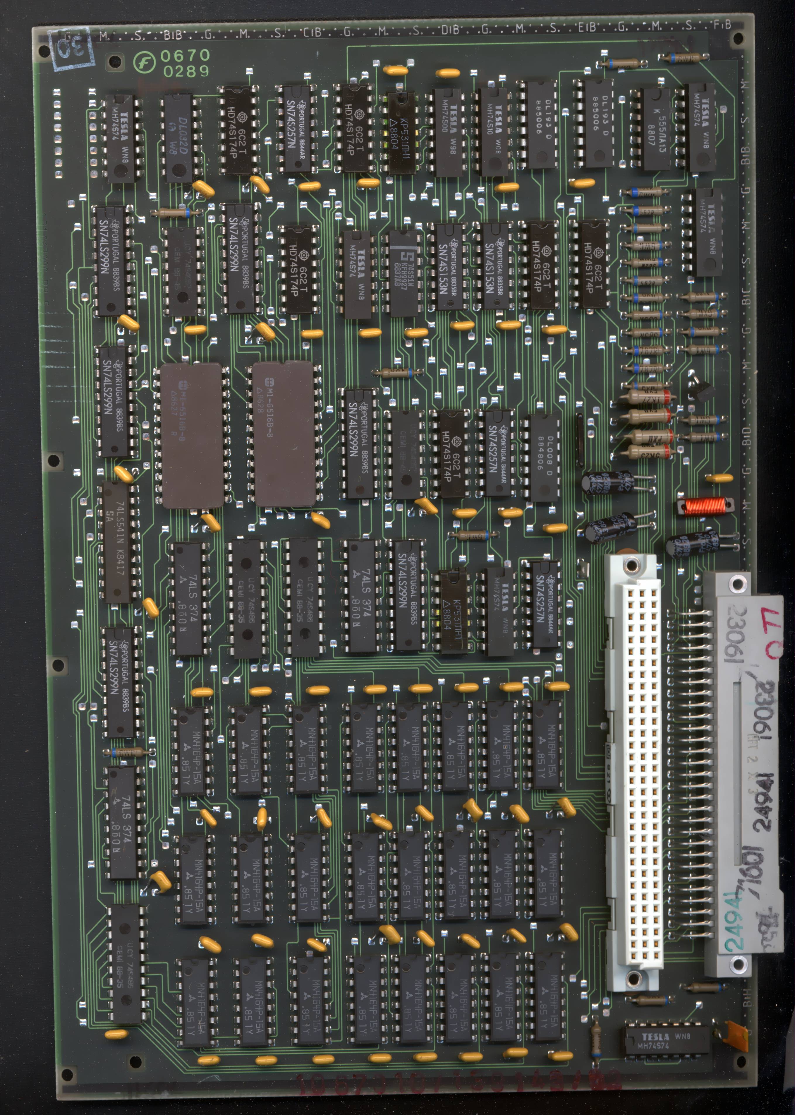
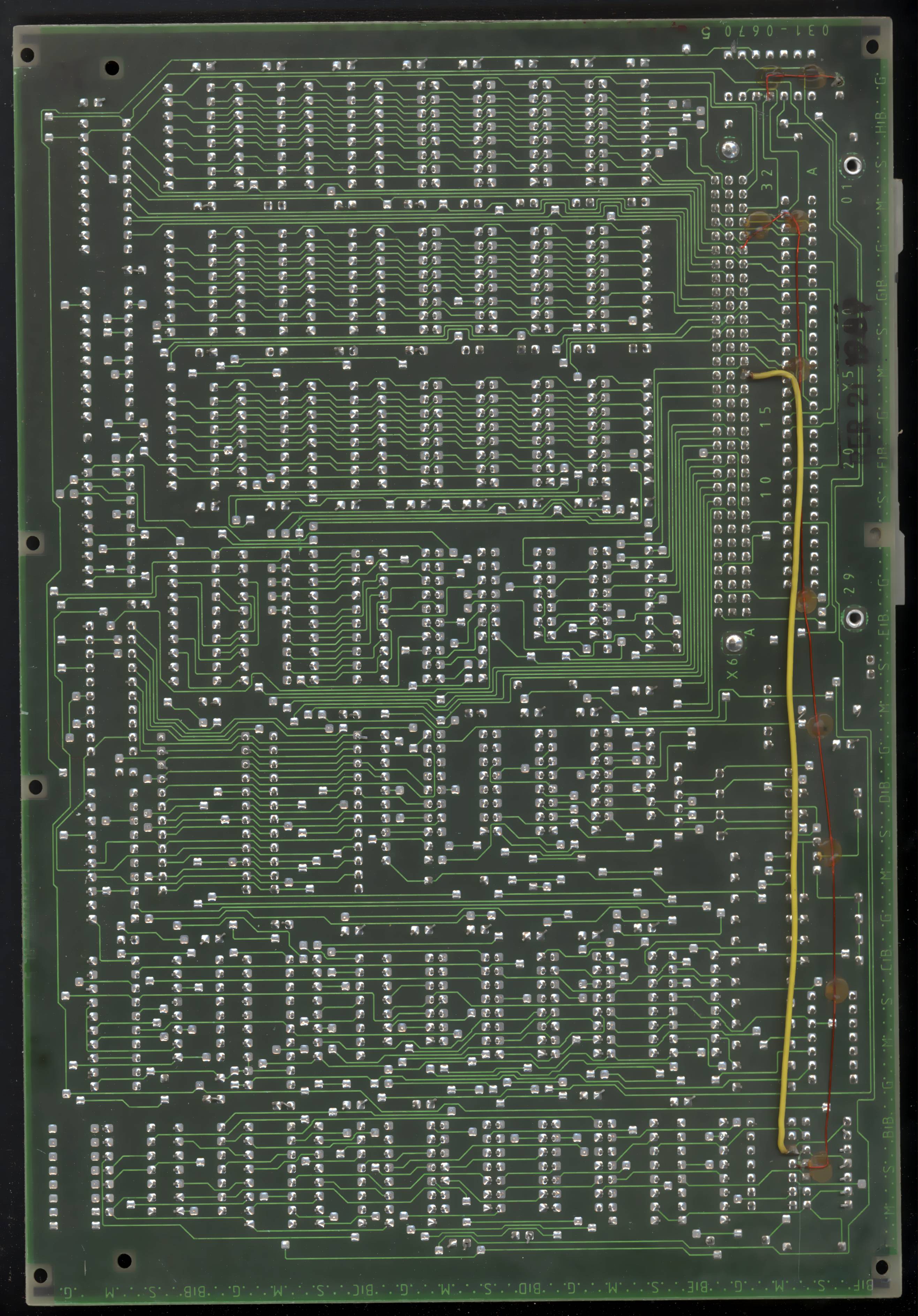
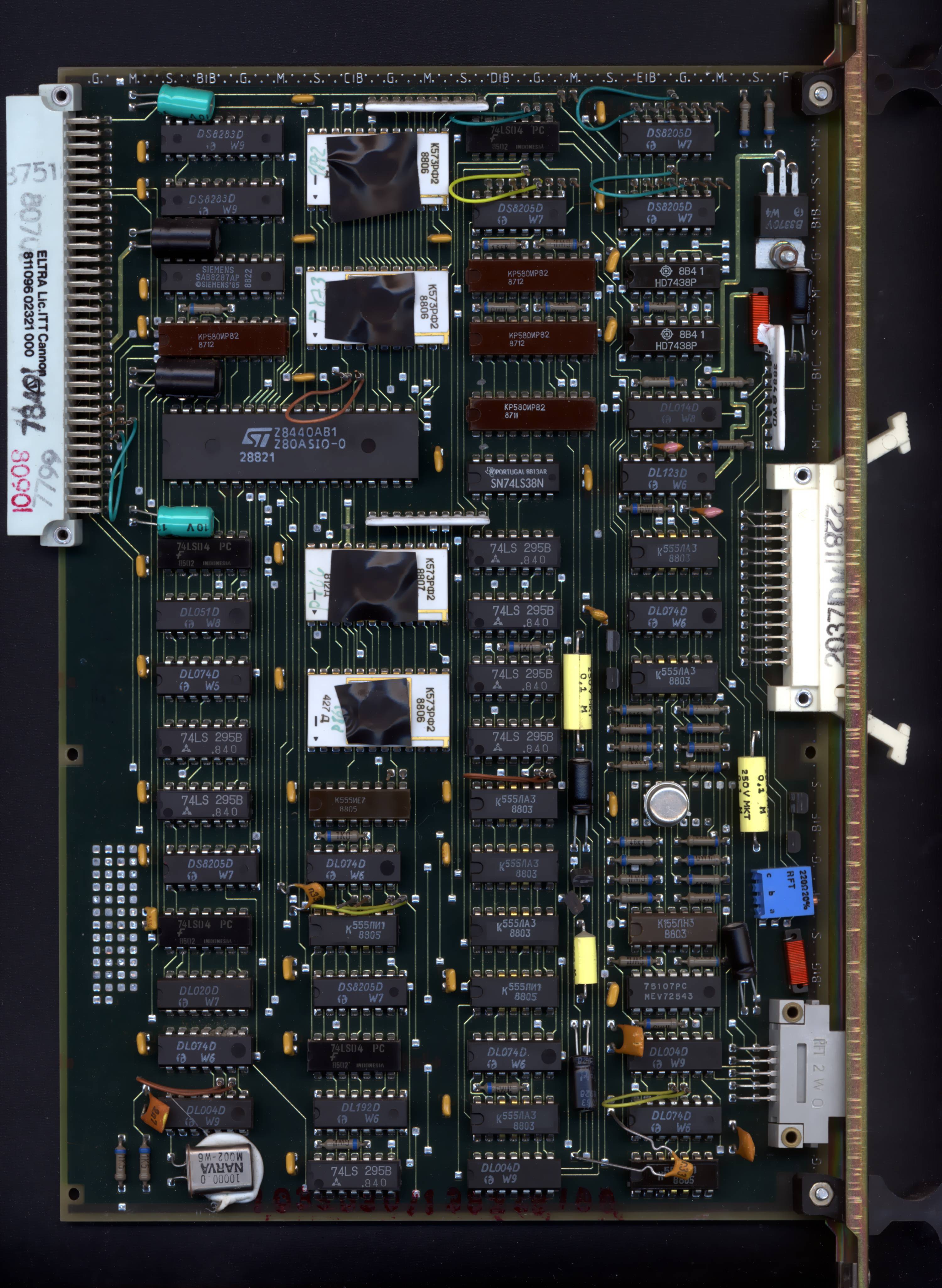
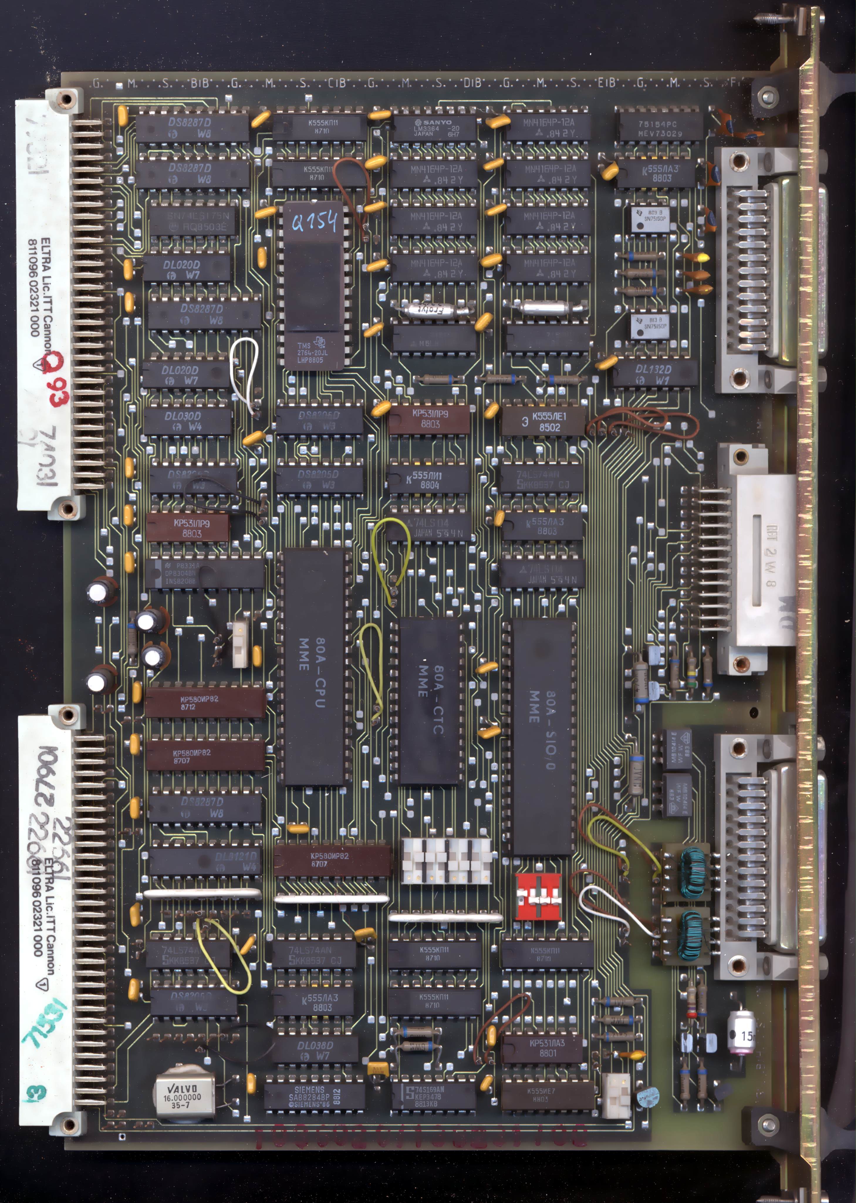
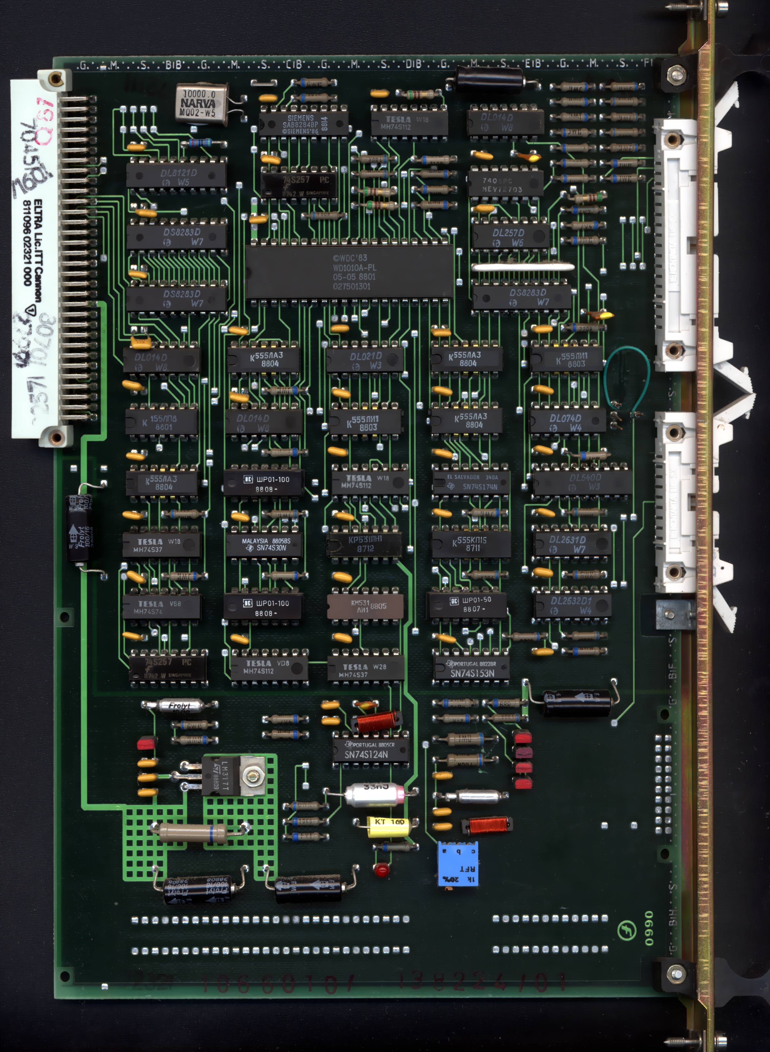
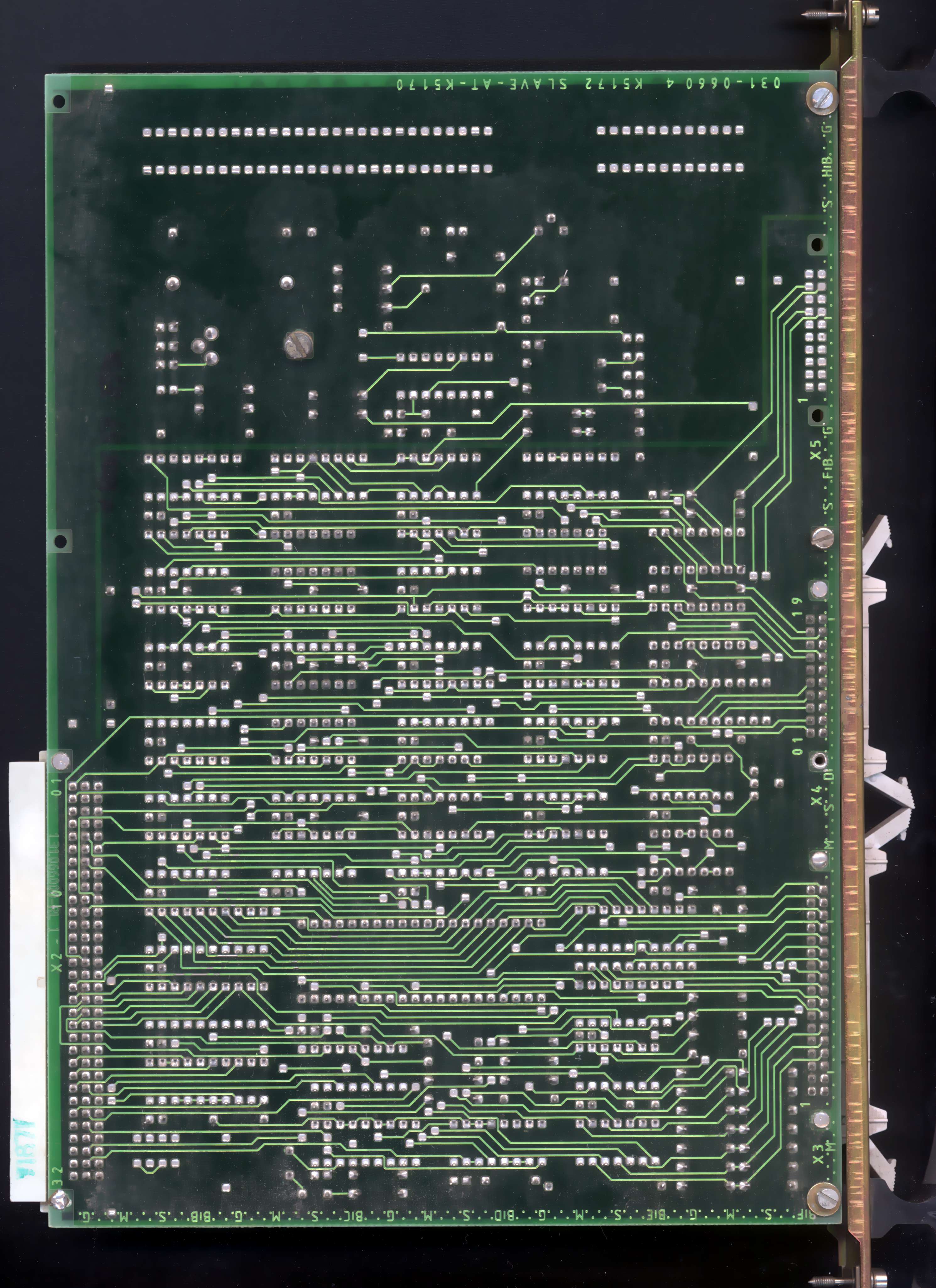
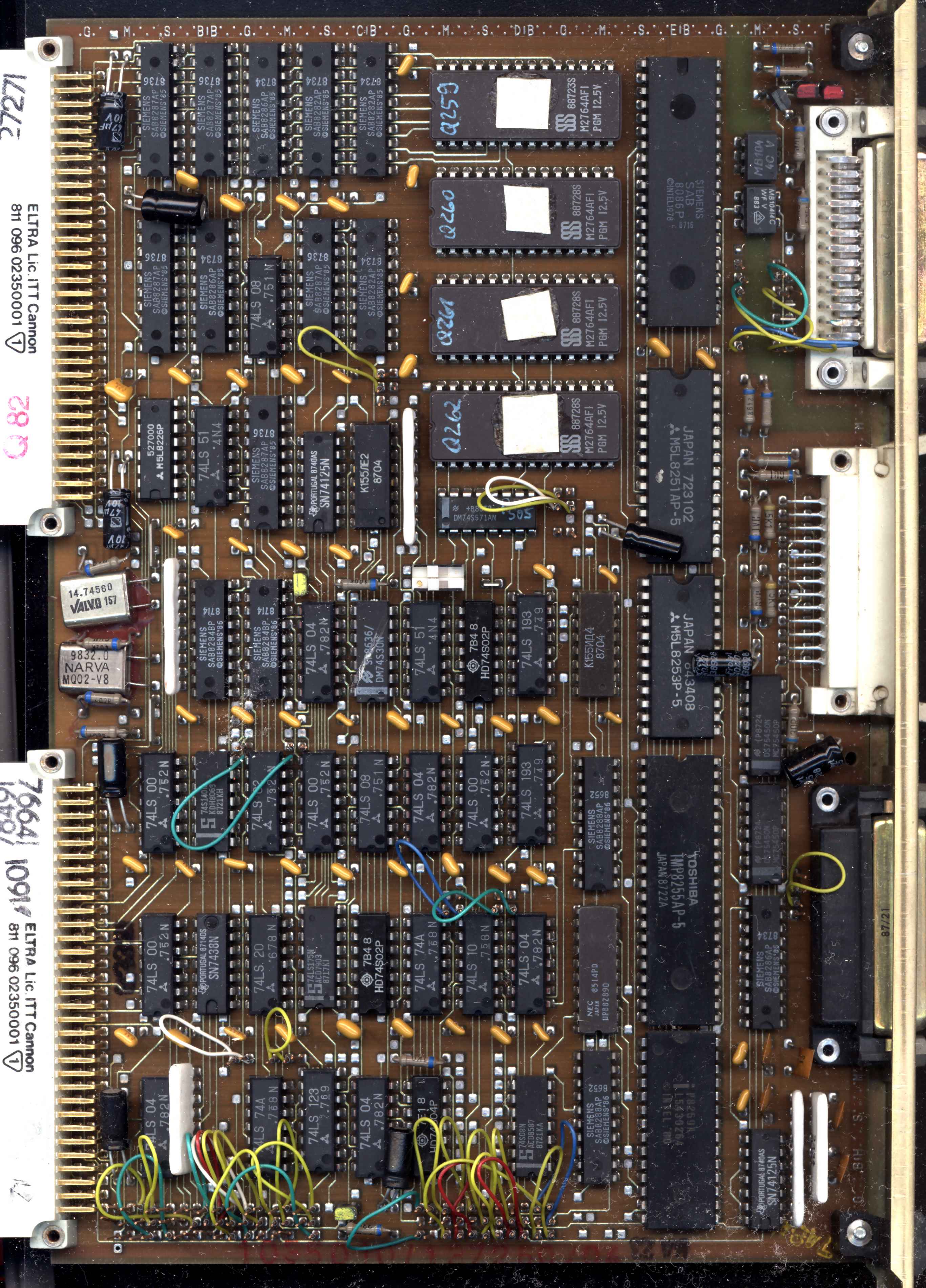
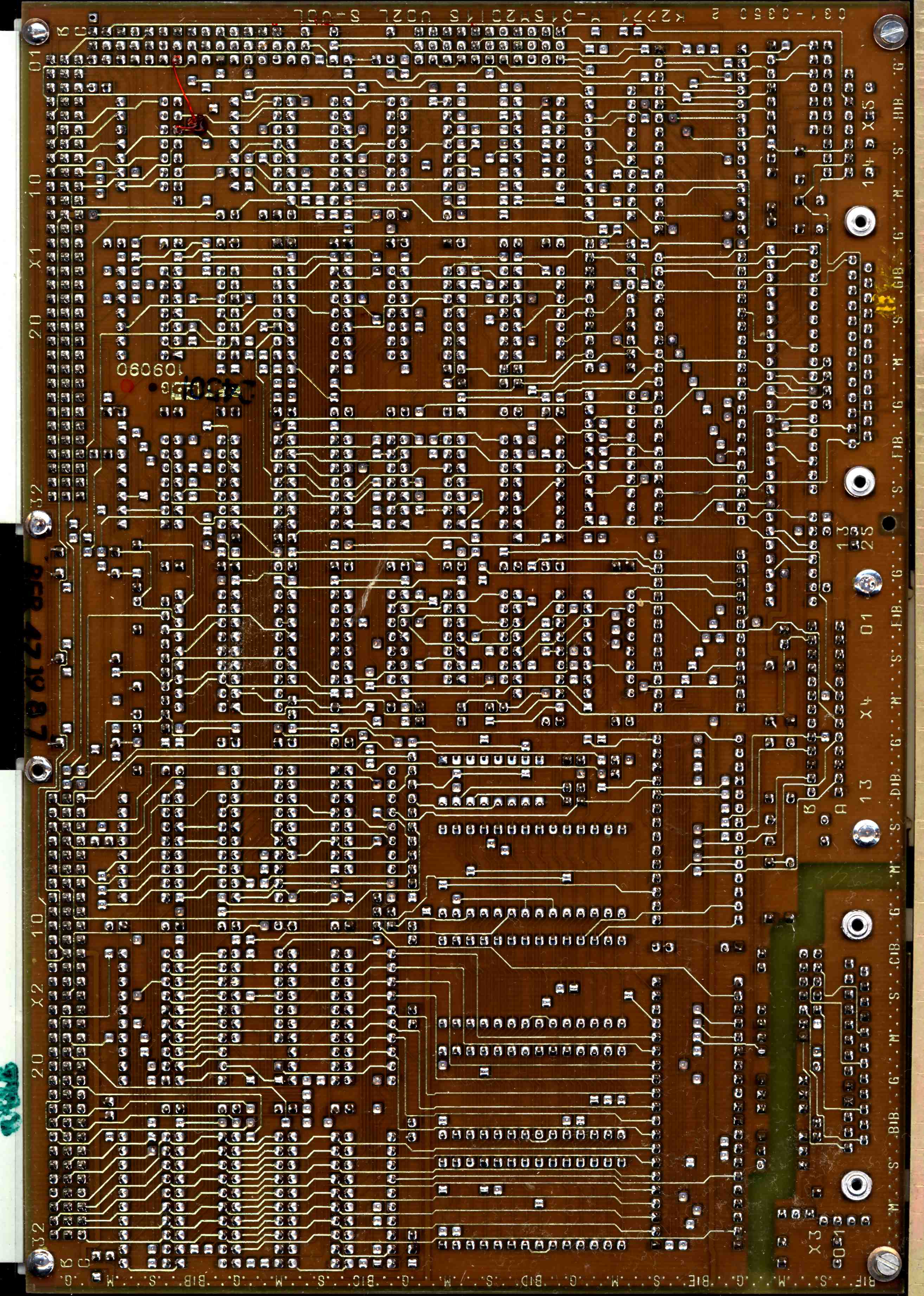
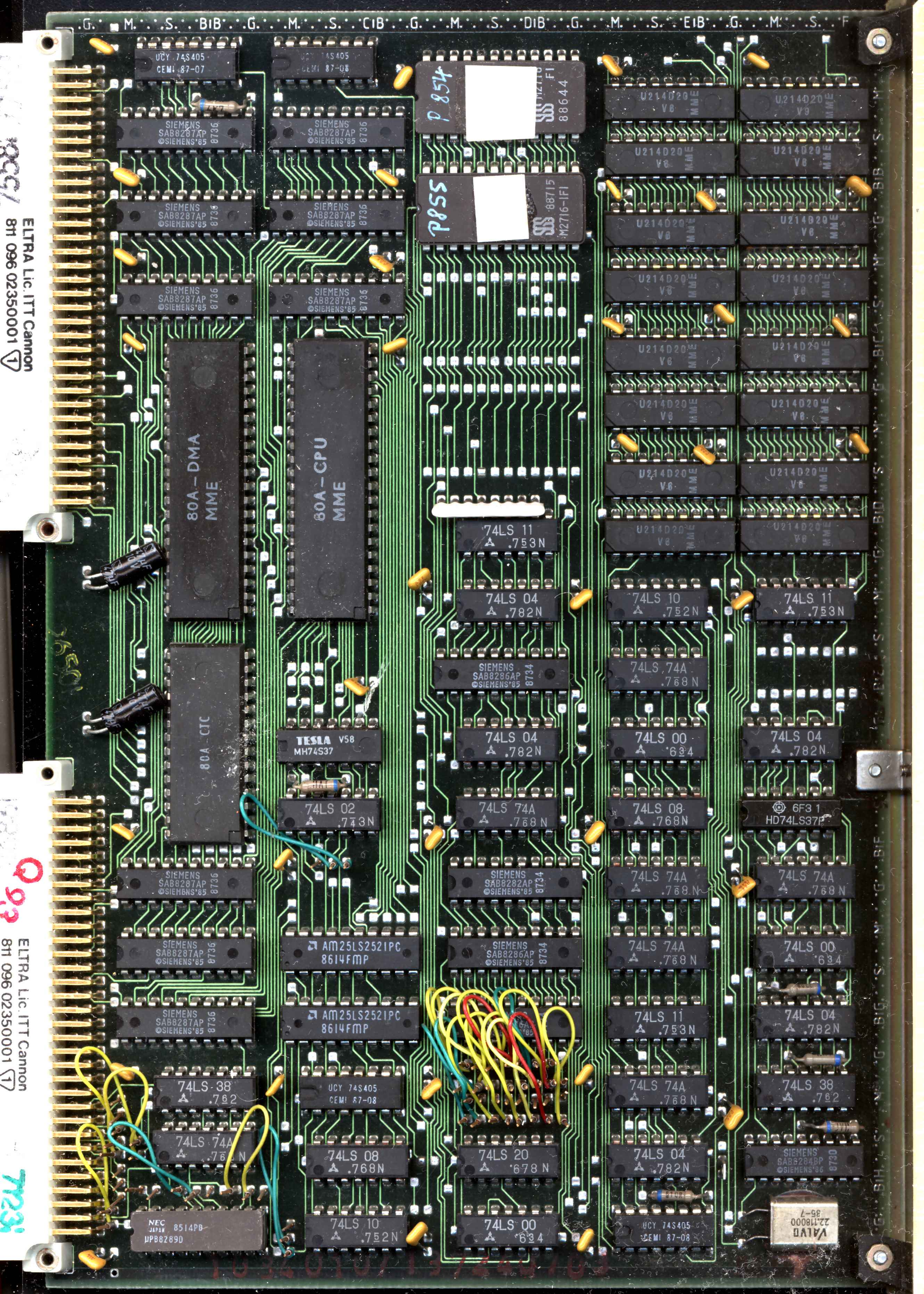
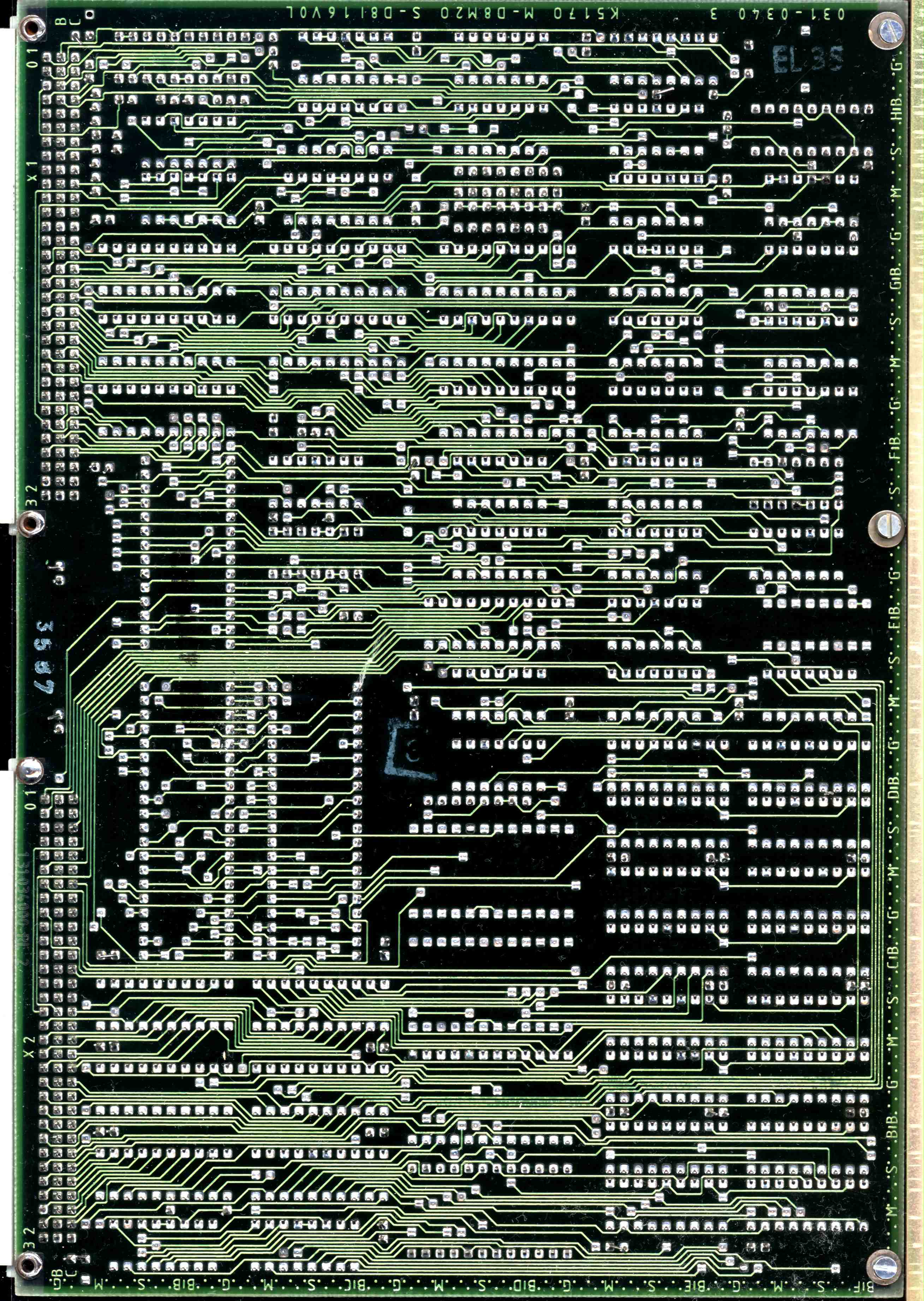
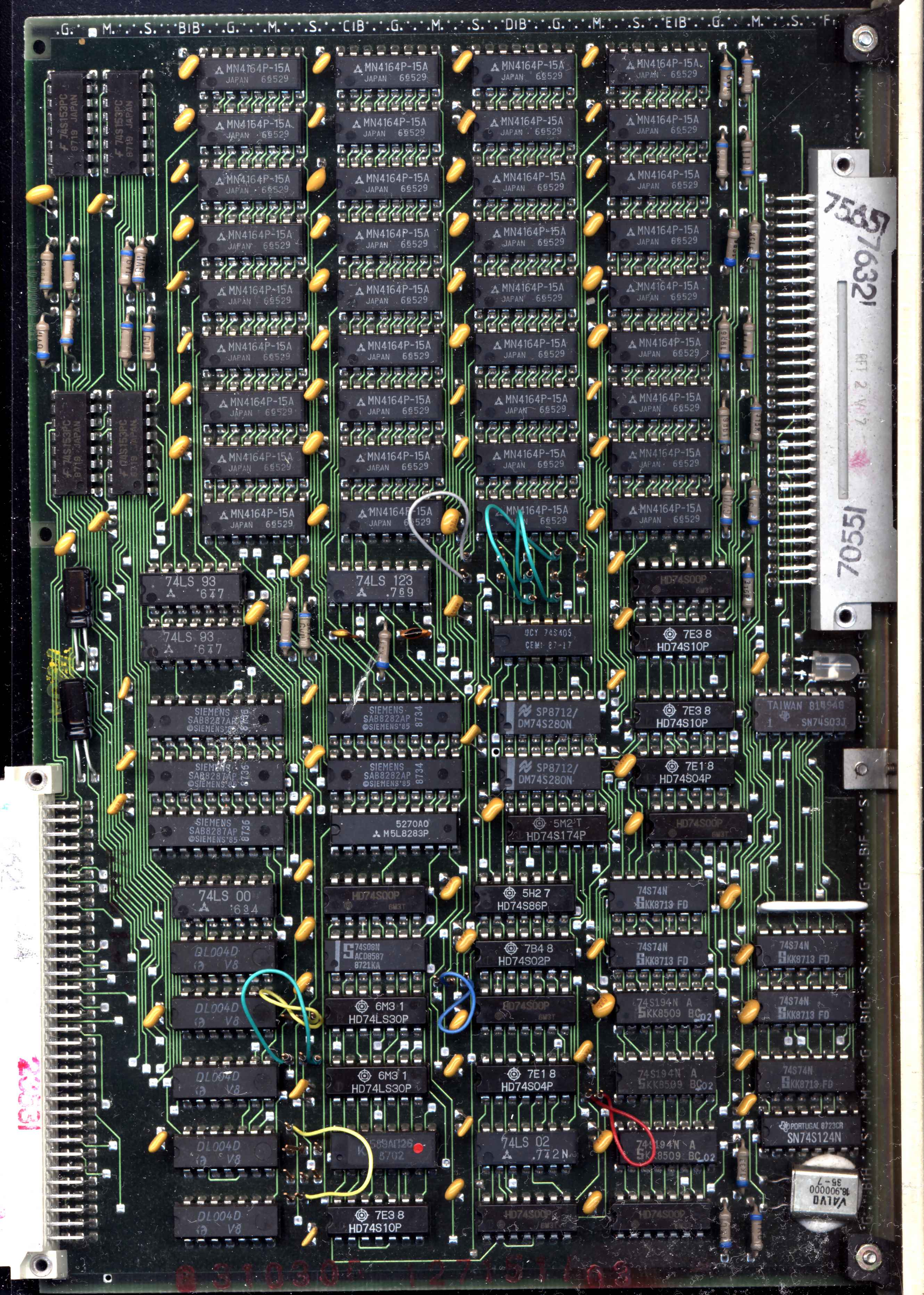
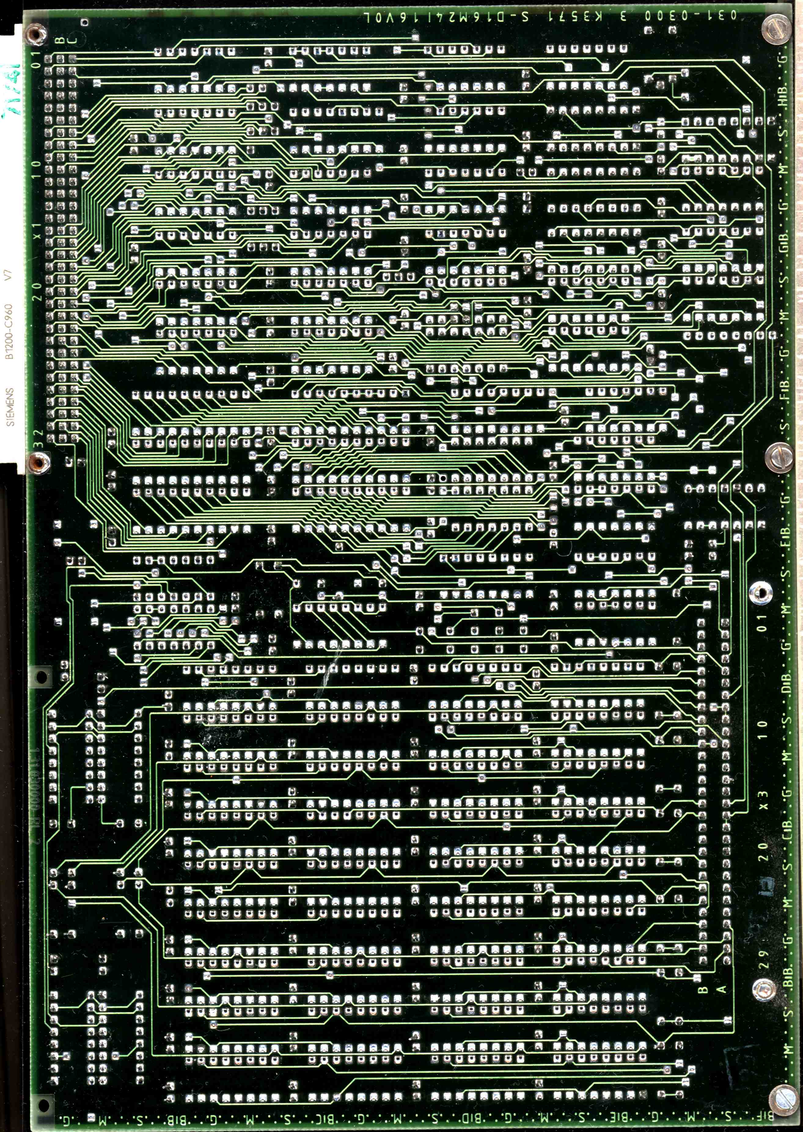
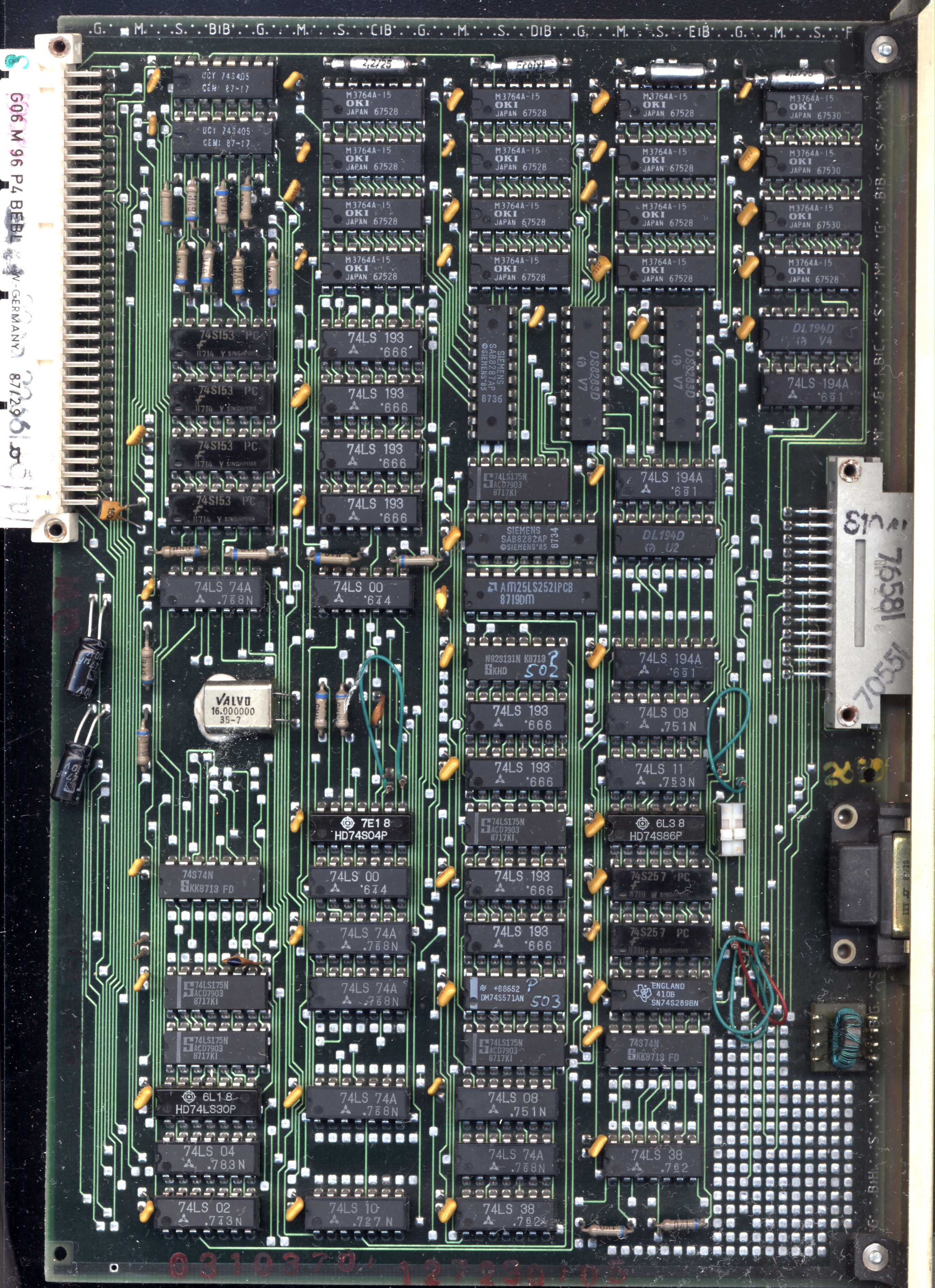
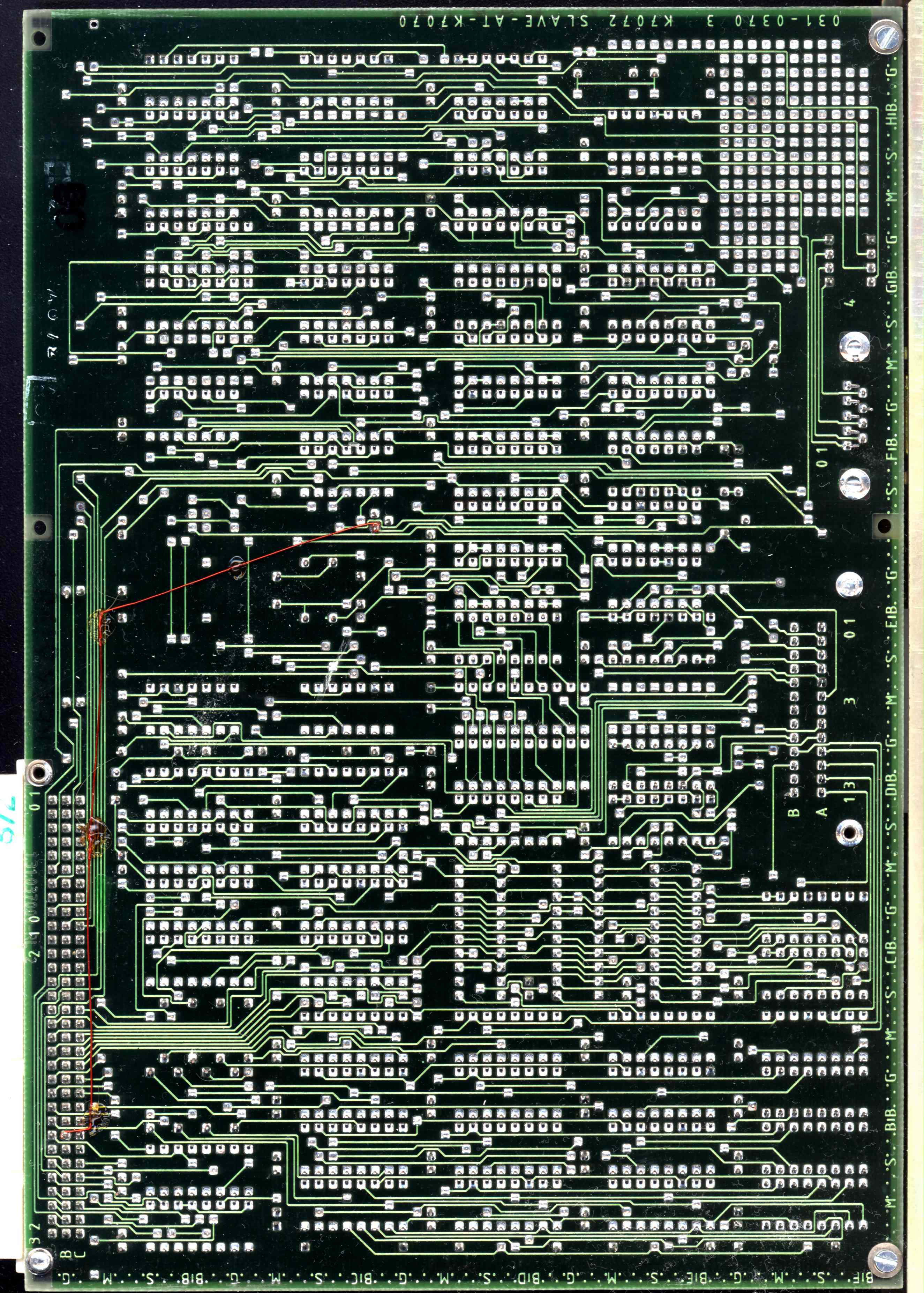
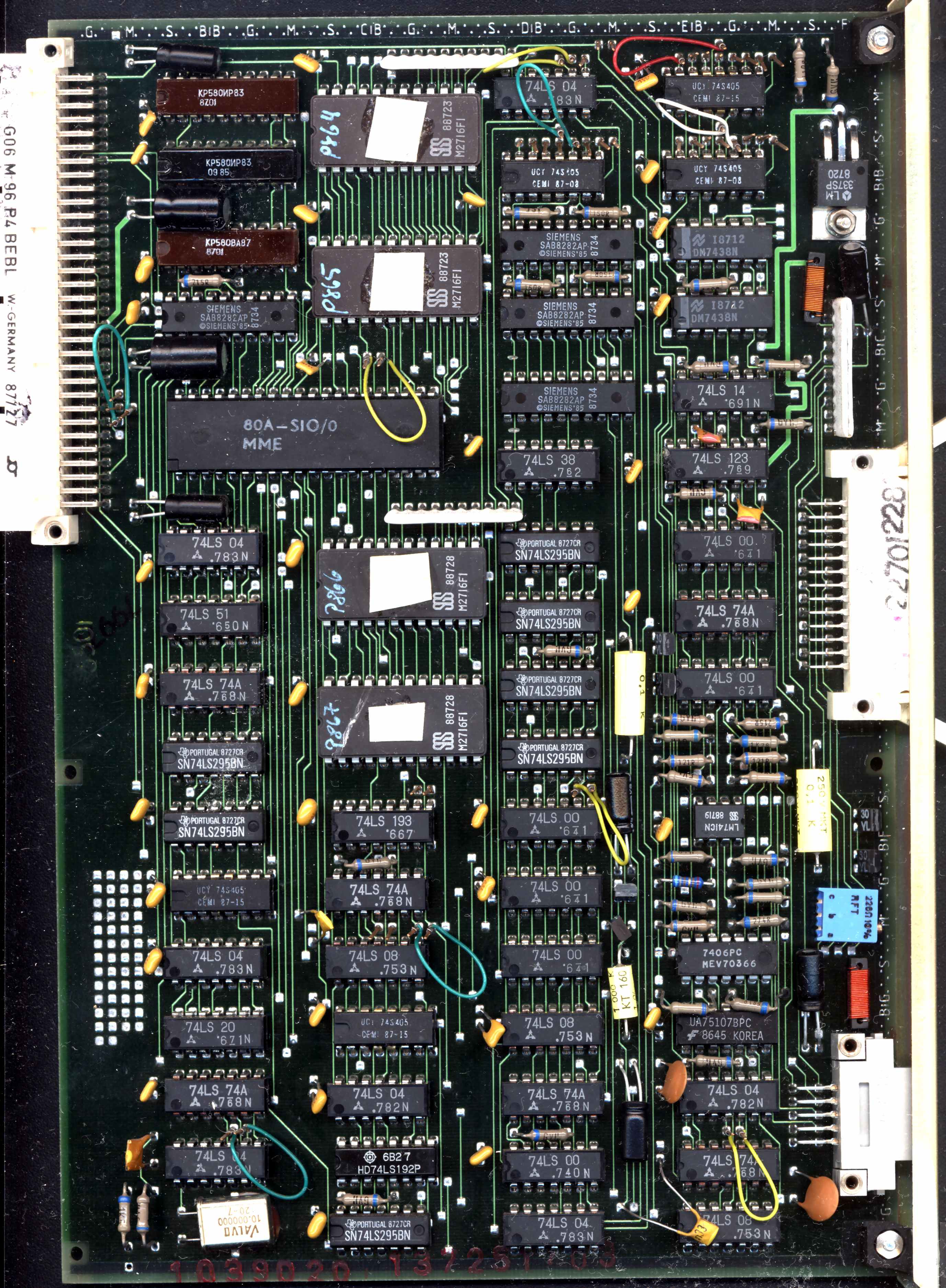
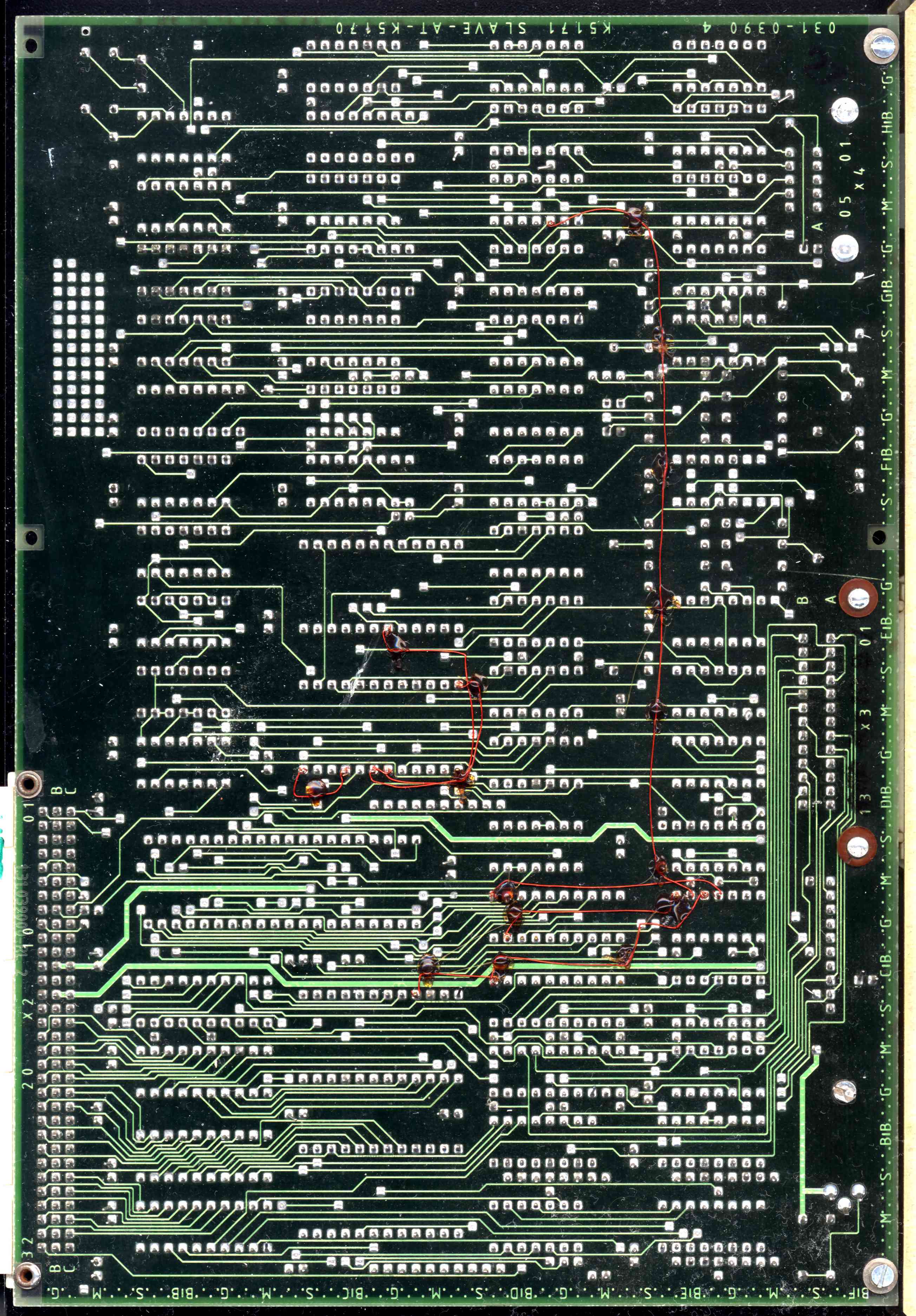
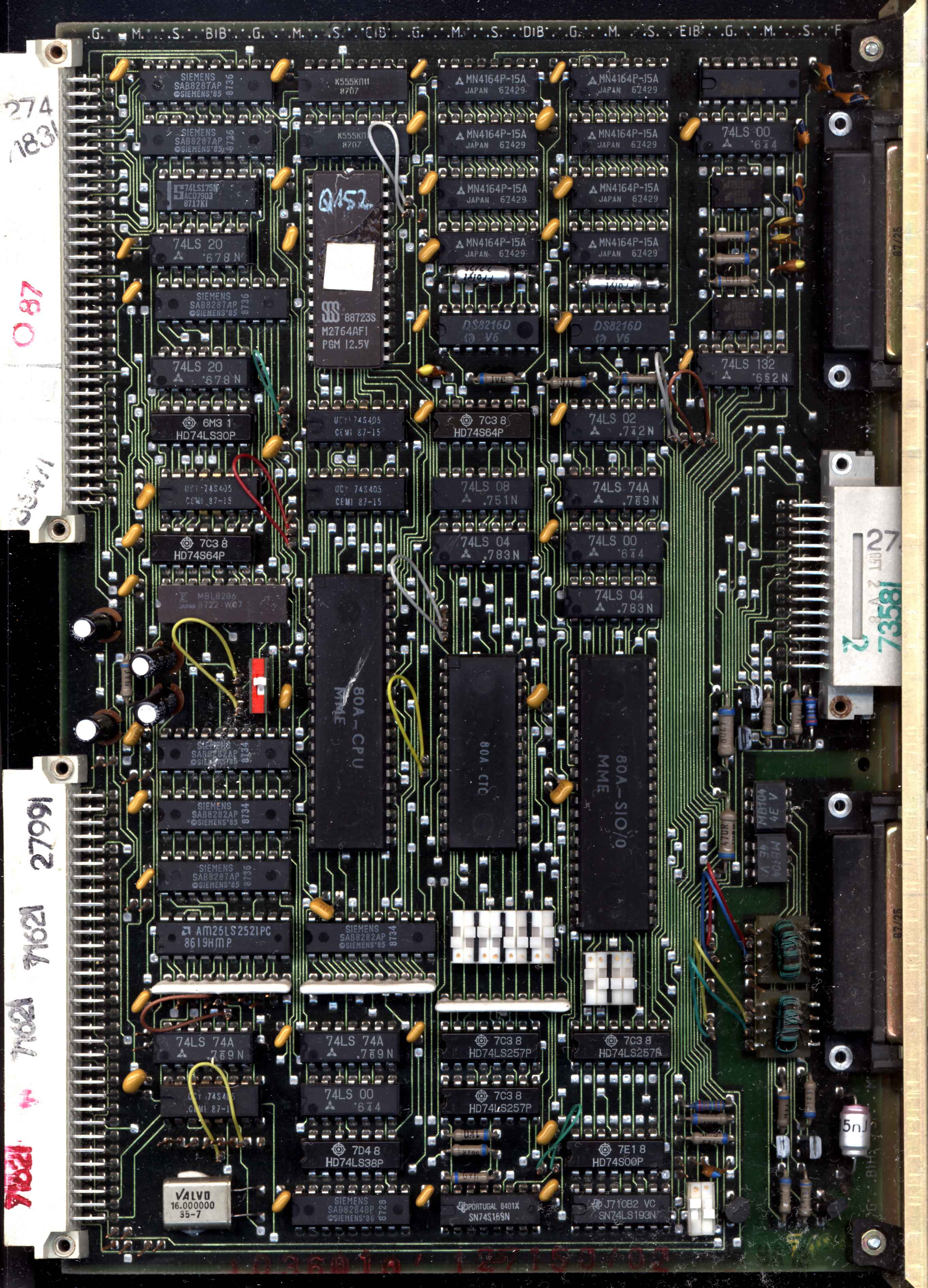
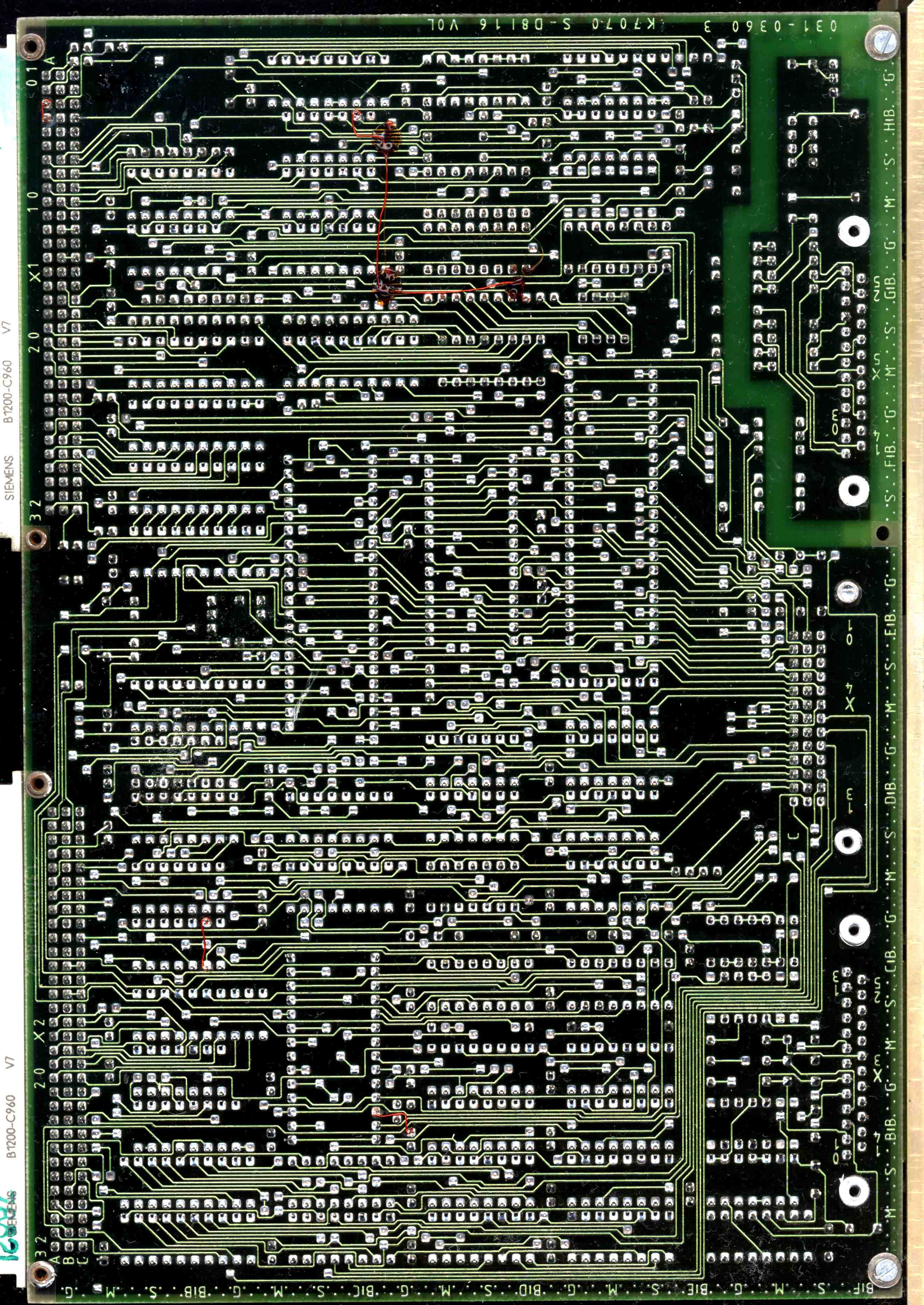
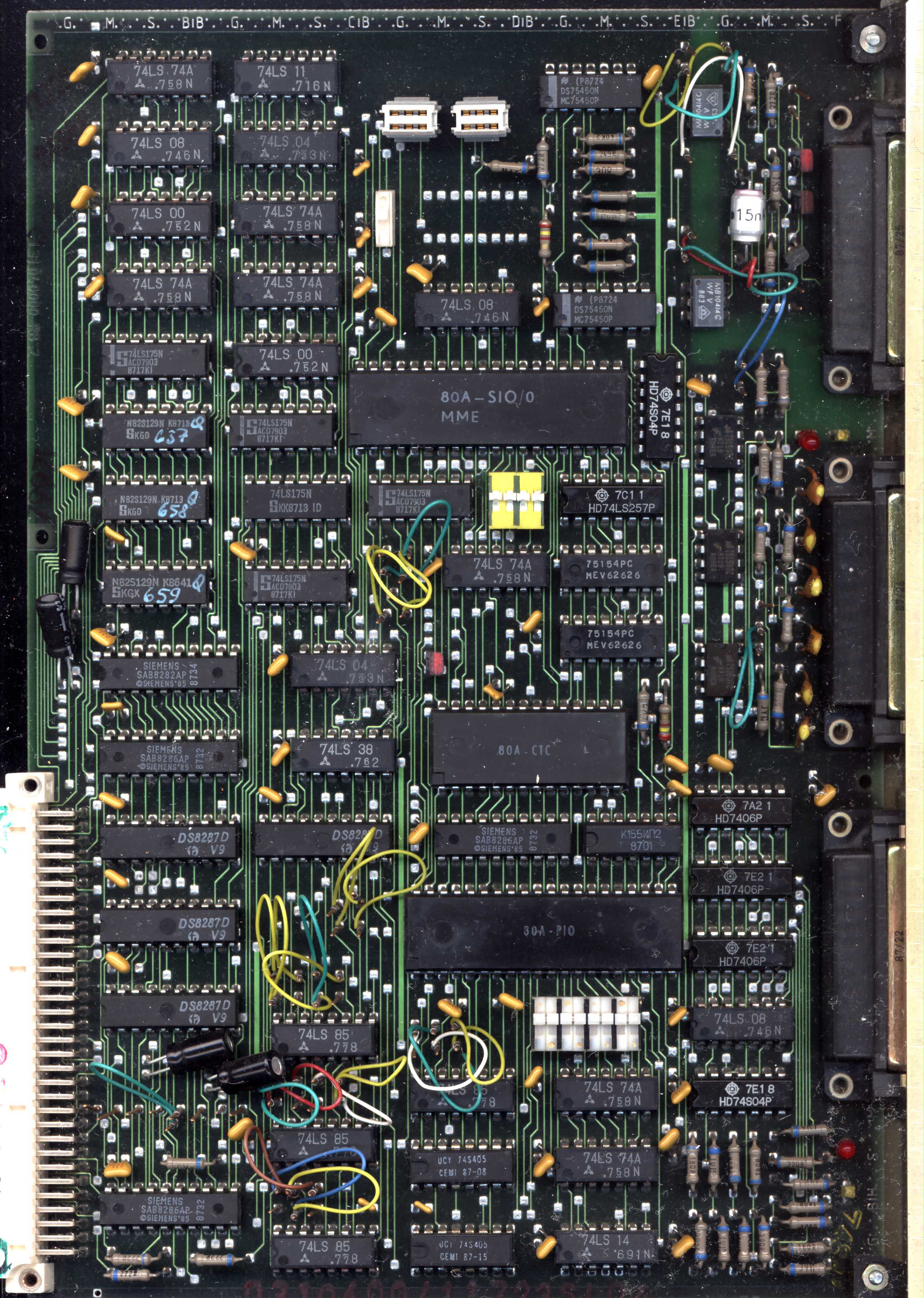
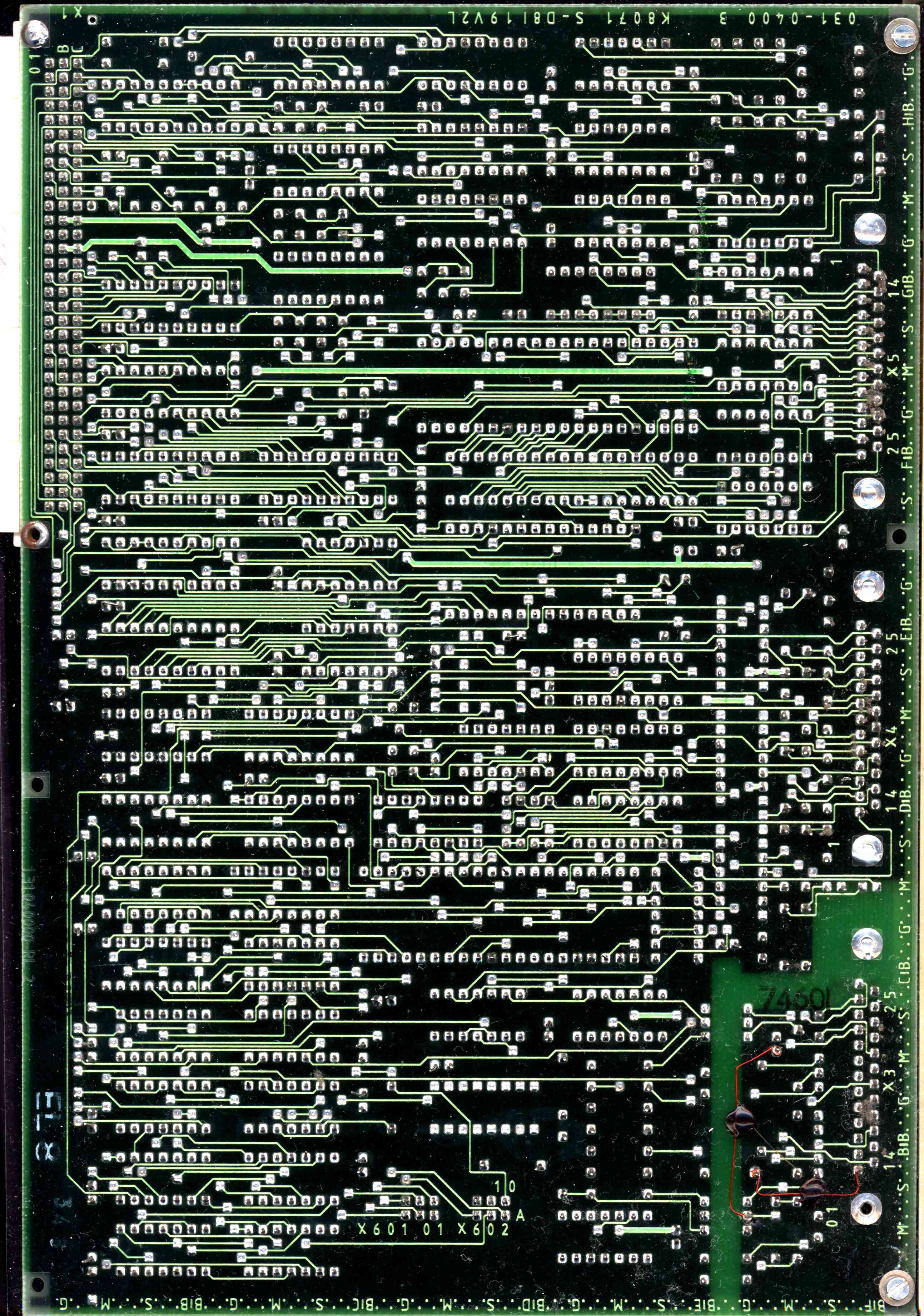
Boards scans
Scans of different boards of A7150:
WARNING: These files are LARGE. 1MB each at least. You have been warned.
| Name | Component | Solder | Name | Component | Solder | |
| K2771.30 ZRE CPU board |
 |
 |
K5170 KES Media controller
|
 |
 |
|
| K3571 OPS 256kB RAM |
 |
 |
K7075 ABG Video card |
 |
 |
|
| K3571 OPS 256kB RAM (second board) |
 |
 |
as above Video card's daughterboard
|
 |
 |
|
| K8071 ASP Serial/Parallel port controller |
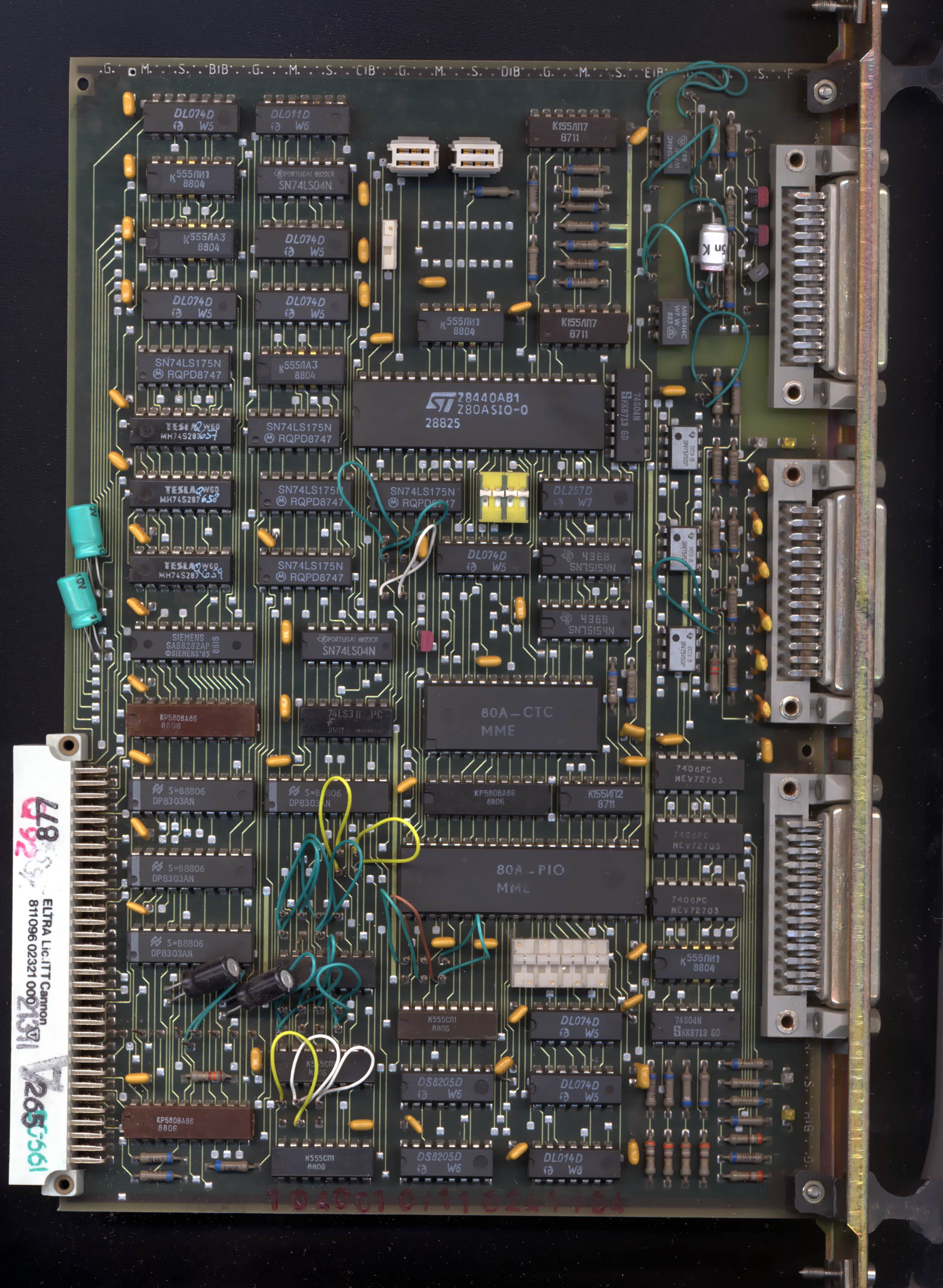 |
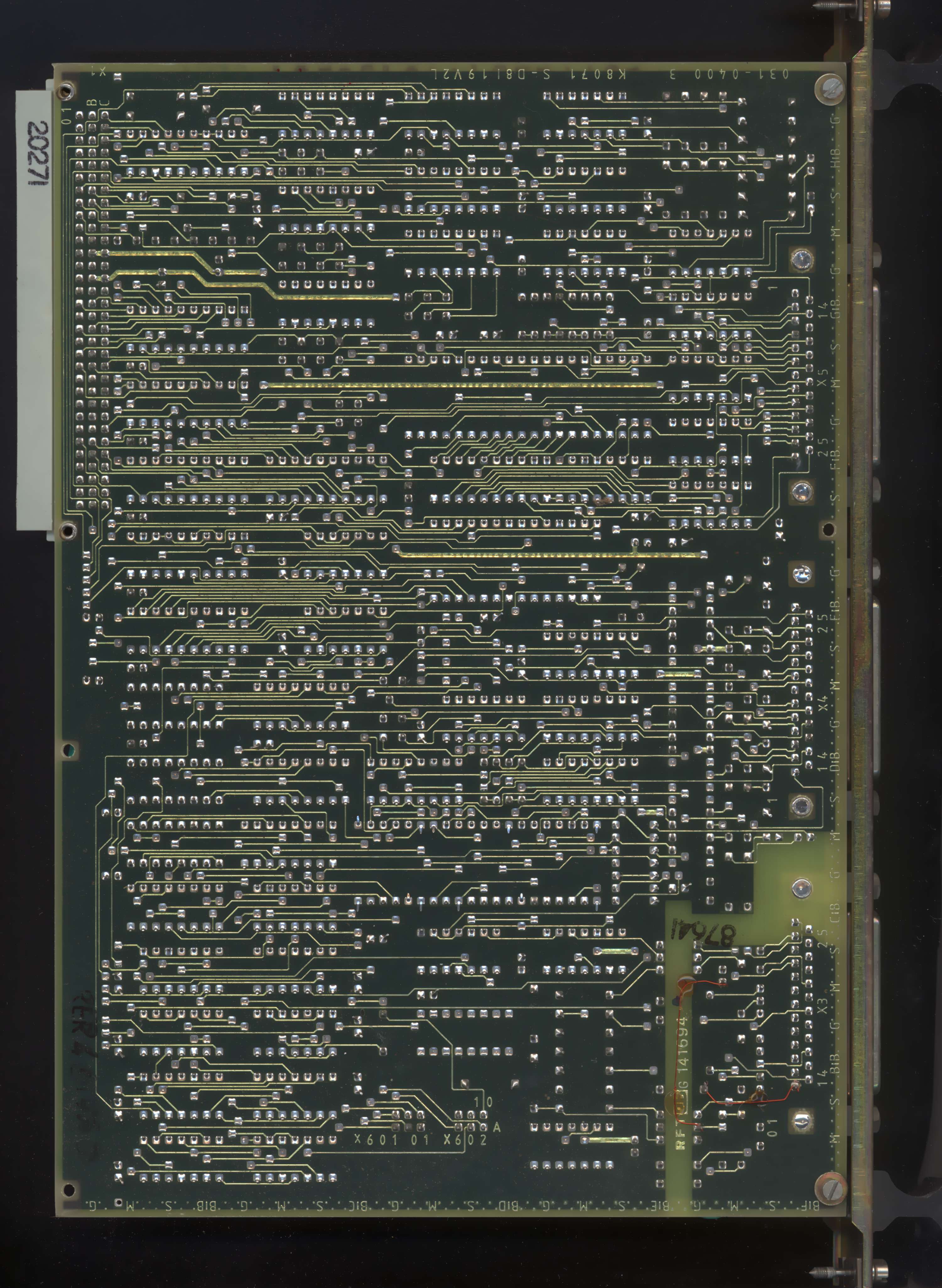 |
K5171 AFS Floppy disk drives controller
|
 |
 |
|
| K7070 KGS Graphics terminal |
 |
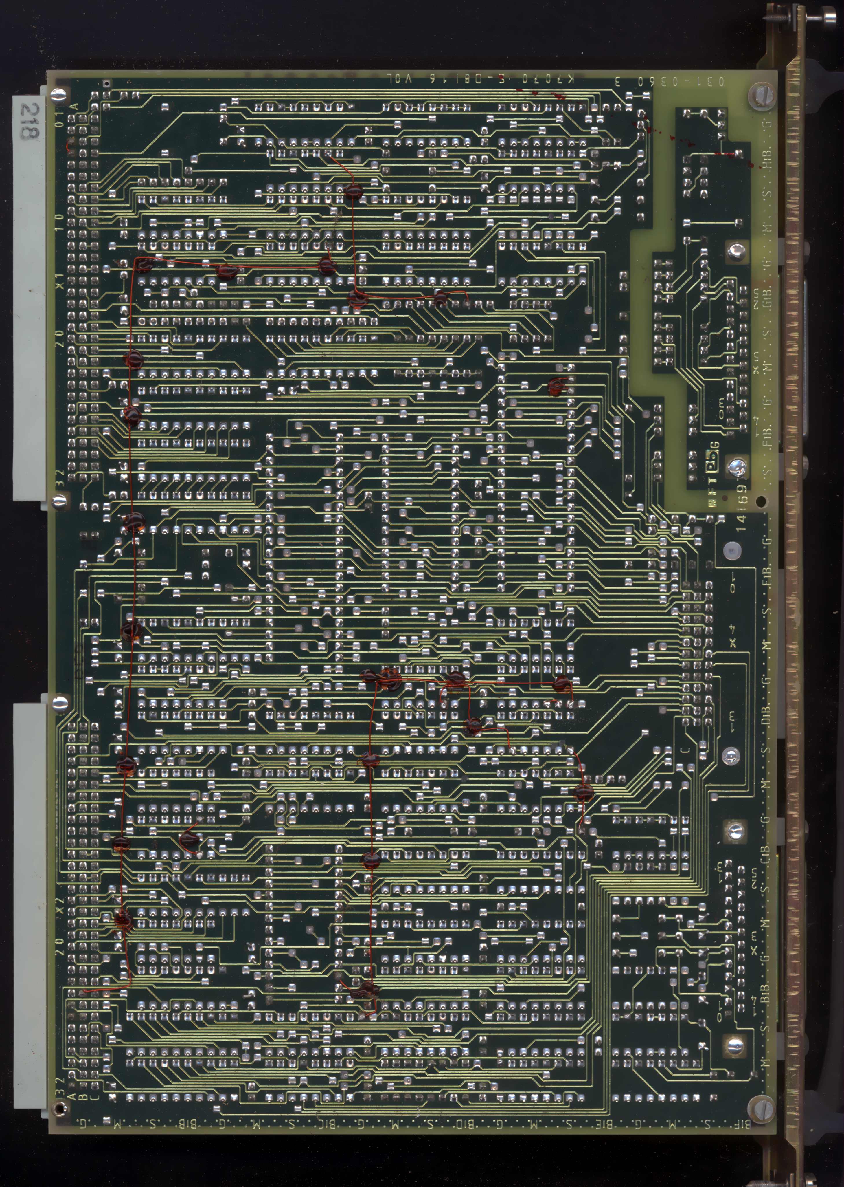 |
K5172 AFP Hard disk drive controller
|
 |
 |
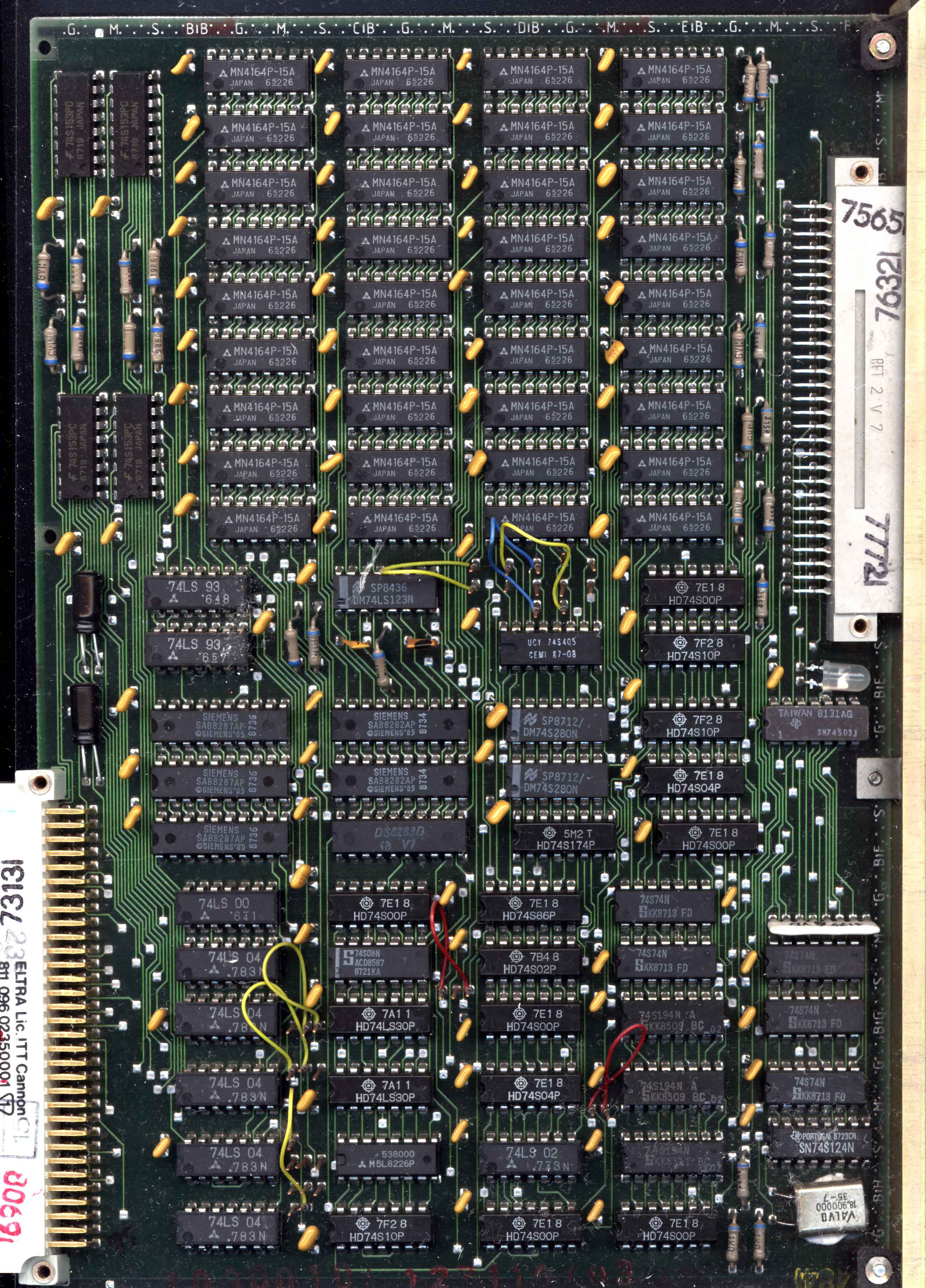
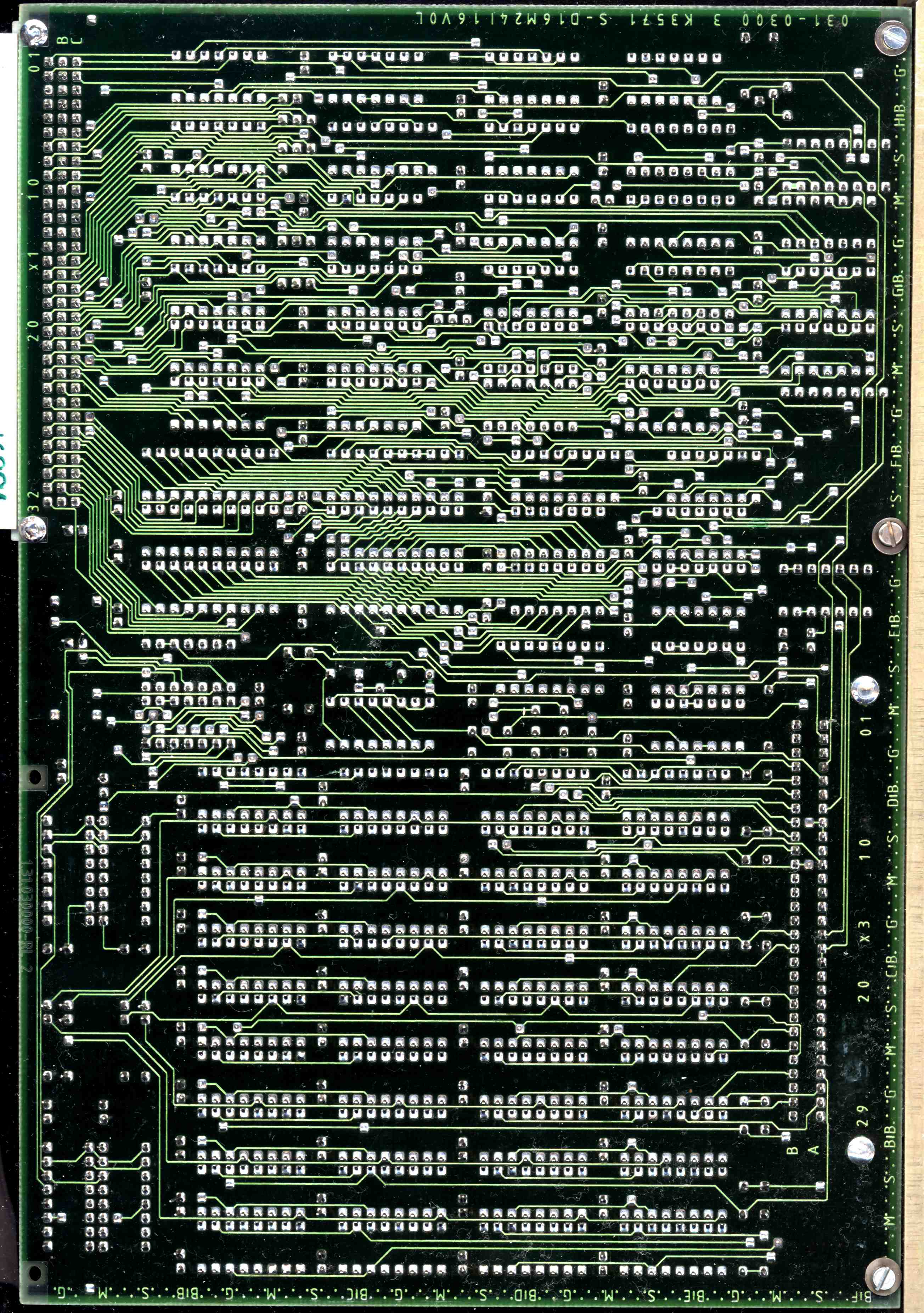
And A7100:
| Name | Component | Solder | Name | Component | Solder | |
| K2771.10 ZVE CPU Board |
 |
 |
K5170 KES Media controller |
 |
 |
|
| K3571 OPS 256kB of RAM |
 |
 |
K7072 ABG Video card |
 |
 |
|
| K3571 OPS 256kB of RAM |
 |
 |
K5171 AFS Floppy disk drives controller |
 |
 |
|
| K7070 KGS Graphics terminal |
 |
 |
K8071 ASP Serial/parallel ports controller |
 |
 |
Important Pinouts:
Video output and how to connect it to VGA monitor for A7150 Color board:

| Pin | Function | VGA DB15 |
| 1 | GND | 5-8, 10 |
| 2 | GND | 5-8, 10 |
| 3 | R | 1 |
| 4 | G | 2 |
| 5 | B | 3 |
| 6 | Video | |
| 7 | NC | |
| 8 | VSYNC | 14 |
| 9 | HSYNC | 13 |
The Video signal is the standard monochrome signal which needs
composite sync. In some units with text mode only graphics cards, composite sync signal is located on pin
9. Graphics output is made, using a DB9
connector with specific pinout compatible with Robotron displays.
However, it it possible to build a converter to connect Robotron to VGA
monitor.
In fact, Robotron never manufactured a nice monitor for this computer to
take full advantage of 640x480 mode.
Pinout of monitor connector of A7100 with grayscale board:
| Pin | Function |
| 1 | GND |
| 2 | GND |
| 3 | nc |
| 4 | nc |
| 5 | nc |
| 6 | VIDEO1 |
| 7 | VIDEO2 |
| 8 | nc |
| 9 | CSYNC |
All outputs are open-collector. VIDEO1 and VIDEO2 are TTL signals of video levels, giving 4 shades from pure black to pure green. Sync is composite, ?26kHz?. The original monitor was Robotron K7229.24 and can't be easily replaced with other monitors.
WARNING: If you have such monitor without cable, there is a cable connector on its mainboard. Numbers of pins in schematic are wrong. The proper is: CSYNC, then free pin, then VIDEO2, VIDEO1. Each cable in grounded sleeve If you need to make cable, compare your PCB with schematic.
Links:
http://www.robotrontechnik.de/index.htm?/html/computer/a7150.htm -
In Robotron Technik site. All boards explained
http://9hal.ath.cx/usr/digital-ag/archiv/ - Look for "A7150 Band 1 -
Rechner und Gerate".
http://www.tiffe.de/Robotron/MMS16/ - Technical documentation and
ROM dumps
http://a7100emulation.npage.de/neuigkeiten.html - A7100 emulator
http://www.ansealk.ru/ftp/OLD_COMPUTERS/ - Quite useful downloads
site with Eastern-block computer bootdisks.
http://oldcomp_strannik.pdp-11.ru/RobotronA7150.htm - In Russian
collection - nice photos of boards
http://web.archive.org/web/20060505141645/http://www.trust-us.ch/chalisti/chalisti_07/007_GFAA.html
- This is in German, something about developing Unix on robotron.