![]()
![]()
![]()
![]()
![]()
![]()
![]()
![]()
![]()


All my content and ptohos

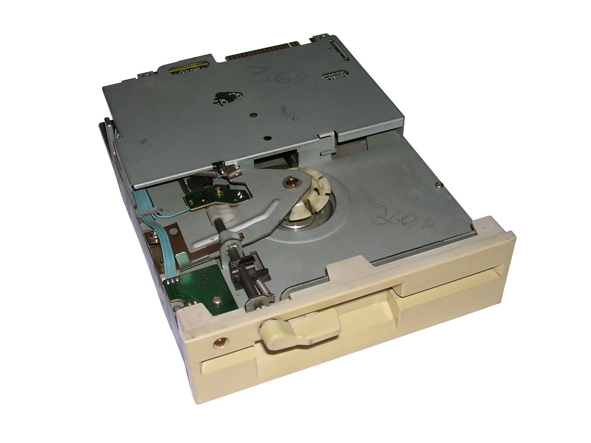
5.25" floppy disks
8 inch floppy disks were first popular floppy disks. They were used in nearly all aspects of computing in 1970s and early 80s.
These floppy disks were used in computers, workstations, microcomputers, industrial analysers and machine driving computers, and even in some terminals.
| Manufacturer: different |
|
||
| Type: Disks | |||
| Capacity: 80kB-500kB, some had 980-1200kB. | |||
|
Fortunately, most PCs will work with many 5.25" drives, they only must be jumper-configured do DS1, not DS0. It's needed in BIOS to set it as 1.2MB or 360K. Very old drives, such as these from CP/M machines (Quad-density) usually won't work well. Disks from microcomputers (Commodore, Atari) may be modulated in GCR, not MFM, so they won't be readable/writable easily in PC 5.25" drive. You can use special cables to connect Commodore drive to PC or use some programs to only read these disks, they may work. |
|||
|
Many times you don't have a sleeve to put your disk into. You should keep 5.25" disks in sleeves when not in use, as they have no cover to protect media from dust. Get this PDF, print it out and glue tabs to make a sleeve. If you try to recover old 5.25" disks, especially from high-humidity environment, remember about floppy "hardware virus" - read FAQ for more info.
And don't forget to look at: If you try to use higher
density floppies in lower density drives (like PC disks in
Amiga), you may have problem: Data written in higher density
drive will be usually readable, but erasing them and writing
data may cause errors. |
|||
Downloads for floppy disk? Yes.
|
|||
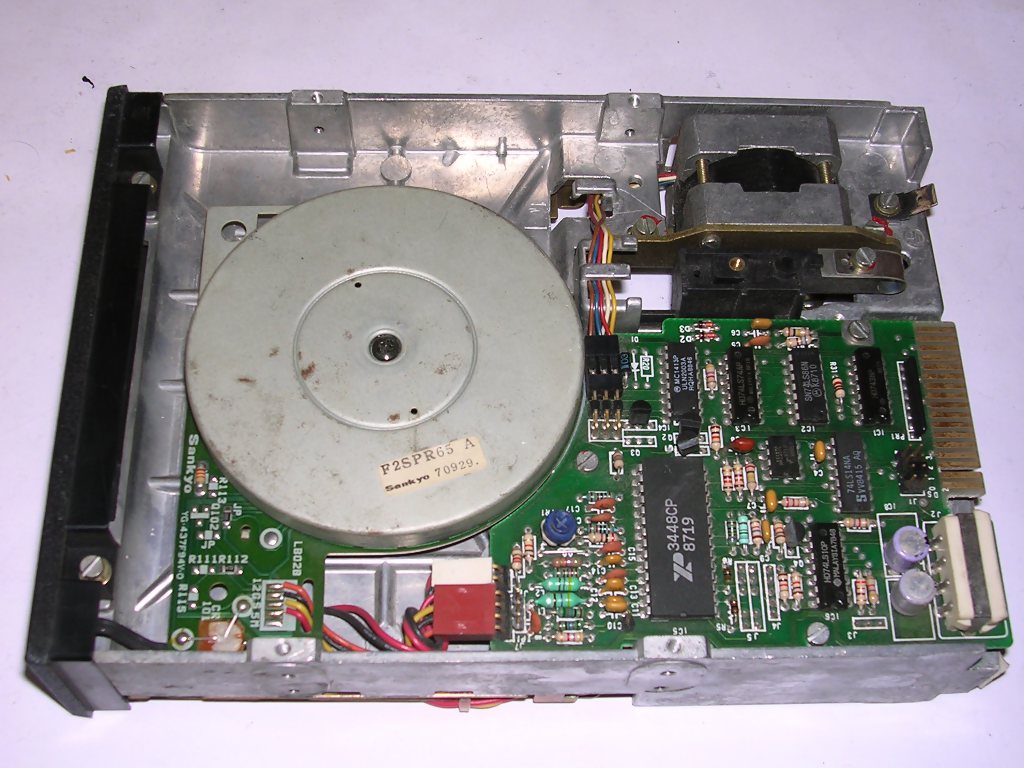
Here you'll see a few examples of 5.25" disks, drives and accessories. You can also look in PCs or 8-bit Micros, as they may have their own floppy disk drives. In these examples you can see what mechanisms are used in floppy drives to move head or disc itself.
Let's describe
typical mechanisms of 5.25" drive: Head (or two on carrier in more
popular two-sided drives) is moved horizontally by stepper
motor. The same time, disc itself is spinned by hub motor. To carry
motion from motor to disc, a locking mechanism with something like a
clutch is used, locking the disc in the shaft of engine. This mechanism
is usually equipped with lever, flap or button to put the upper part
into the hub locking the disc. If it's misaligned or worn out, disk is
kept in lock when lever is unlocked, usually spinning hub makes it
unlock.
To get information about mechanism, a series of mechanical or optical
sensors are used. Typical are:
- Optical barrier looking for write protection and disk change, as if you
change disc you have to break optical barrier for write protection.
- Index hole - in many drives, to monitor for start of tracks, optical
barrier located near the center of the disc. In fact only hard-sectored
disc use it in its typical way.
- Lock monitor - usually mechanical switch used to tell the drive that
it's closed.
- Optical barriers to keep head moving in mechanical constrains.
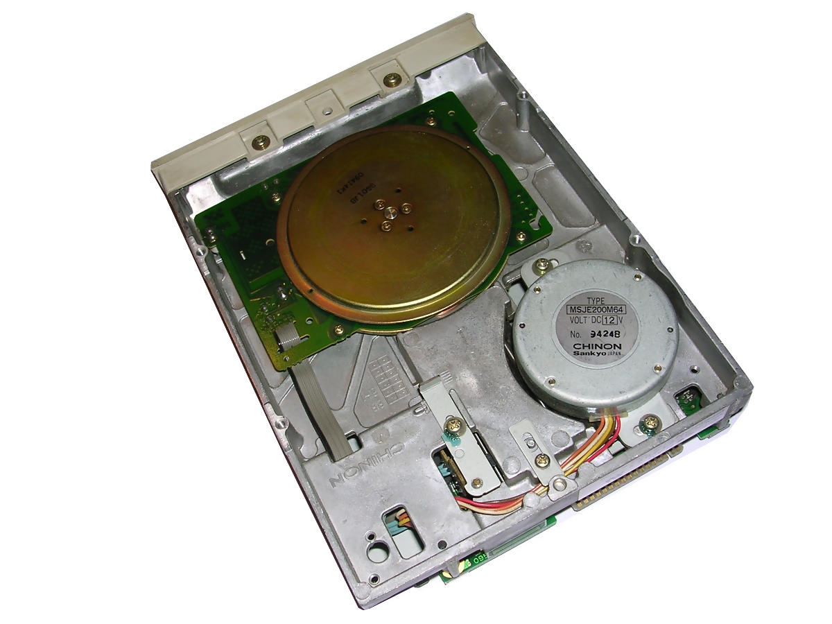
Spinning disc can be realized:
- With precise motor connected to the hub with belt -
popular in early-80s drives, it usually has black and white bars for
stroboscope diagnostics.
- With motor attached with its coils to PCB, used to drive the
shaft directly - popular in most later drives, but harder to service.
Later units allowed to easily switch between 300 and 360RPM without long
callibration.
Moving heads is usually done with:
- Stepper motor pushing head carrier with piece of metal tape. The motor
can be installed with shaft horizontally (usually) or vertically,
perpendicular to head carrier moving axis.
- Stepper motor with shaft covered by worm screw, this screw pushes/pulls
head carrier - shaft is installed parallel to head moving axis. This
technology was used to made smallest drives.
- Stepper motor equipped with a large horizontally-placed wheel, in which
the same worm screw is cut-in. It's used to move head. Used mostly with
success in early German drives, used with less success in Eastern
European drives (as the worm cut was not deep enough).
Some later drives have additional solenoid which is used do drop heads
to the surface of the disc when disc is used and lift heads after
operation. Its action is easy to hear, as it emits quite loud click when
heads are dropped or lifted.
And don't forget about drive electronics. There are usually
some jumpers or pads. The must-have is drive number, which, in PC, must
be always set to DF1 (D1, DRIVE1, ID1 or just 1 in 4-jumper block
numbered starting with 0), even in two-drive systems. There are more
jupers, TEAC Manuals usually describe them, other drives use similar
descriptions. Many times you can see FG jumper which shorts electronics
ground to metal frame ground. INUSE or IU turns pin 4 of connector
to IN USE signal. ML - decides should drive motor be activated by MOTOR
signal in interface cable, or is it only for disk-in-use information
purposes. RY/DC is commonly used to decide should line 34 of connector
be used as READY signal or DISK CHANGE signal.
More rare jumpers: U0 and U1 jumpers are rare, they allow to
invert drive LED signal and to decide whether LED should be turned on (usually
some combos of DRIVE SELECT, IN USE and READY signal, with OR or AND
between). LG - Inverts LOW/HIGH density selection signal line.
Some rare drives use I and IS jumpers to set speed. If I is set, drive
uses dual-speed: 360rpm for high density and 300rpm for low. If I and IS
are off, drive spins 360rpm. If both are on, drive goes dual-speed, but
remains in ready state after changing format by DENSITY line.
E2 - even more rare, used sometimes in hard-sectored drives. Controls
index line of drive.
Here are few disk drives discussed:
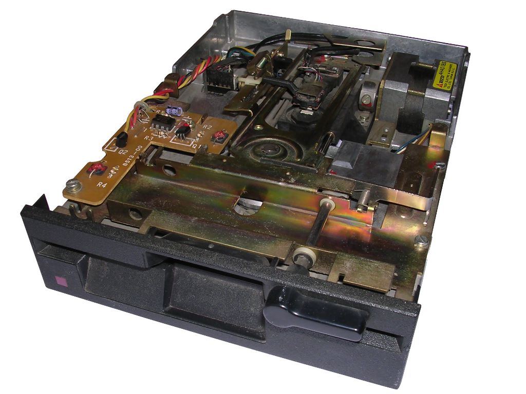
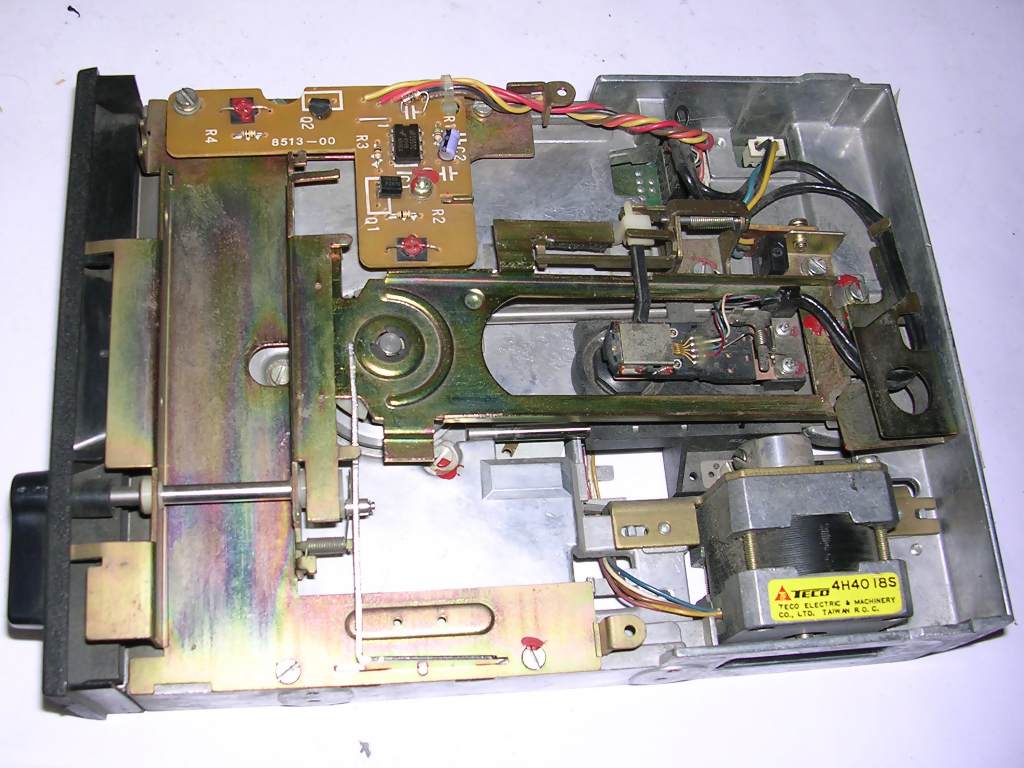
| Alps DFC222B02A | ||
| Density: Double (360K
in PC) Jumpers not described well. Disc motor board described very well, you can see which connections are for which function, making it theoretically possible to alter drive speed. Head assembly covered by piece of metal. Locking mechanism: Turning lever. Head moving mechanism: Stepper motor (shaft horizontally) + steel tape, shaft perpendicular to head moving direction. Spinning mechanism: Motor in PCB. |
 |
|
 |
 |
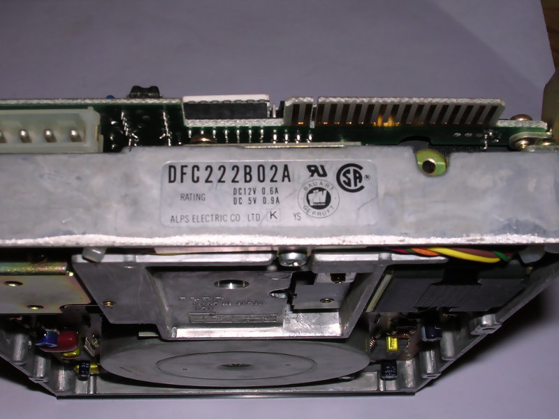 |
| Electronics close-up | Connections are well labeled here... | Notice white termination resistors in socket |
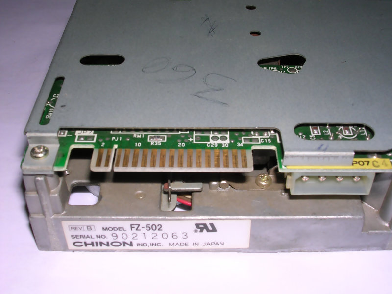
| Chinon FZ-502 | ||
| Density: Double (360K
in PC) Jumpers not described well, visible on the side of PCB. Head assembly and whole upper part covered by piece of metal. Locking mechanism: Turning lever. Head moving mechanism: Stepper motor moving head carrier, shaft located vertically. Spinning mechanism: Motor in PCB. |
 |
|
 |
 |
|
| Notice head moving motor | Connector piece | |
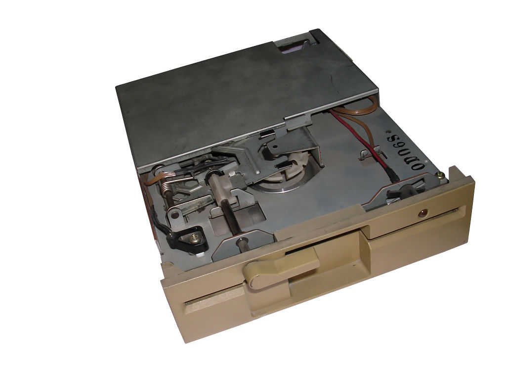
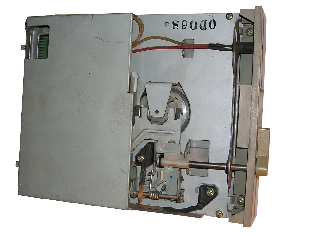
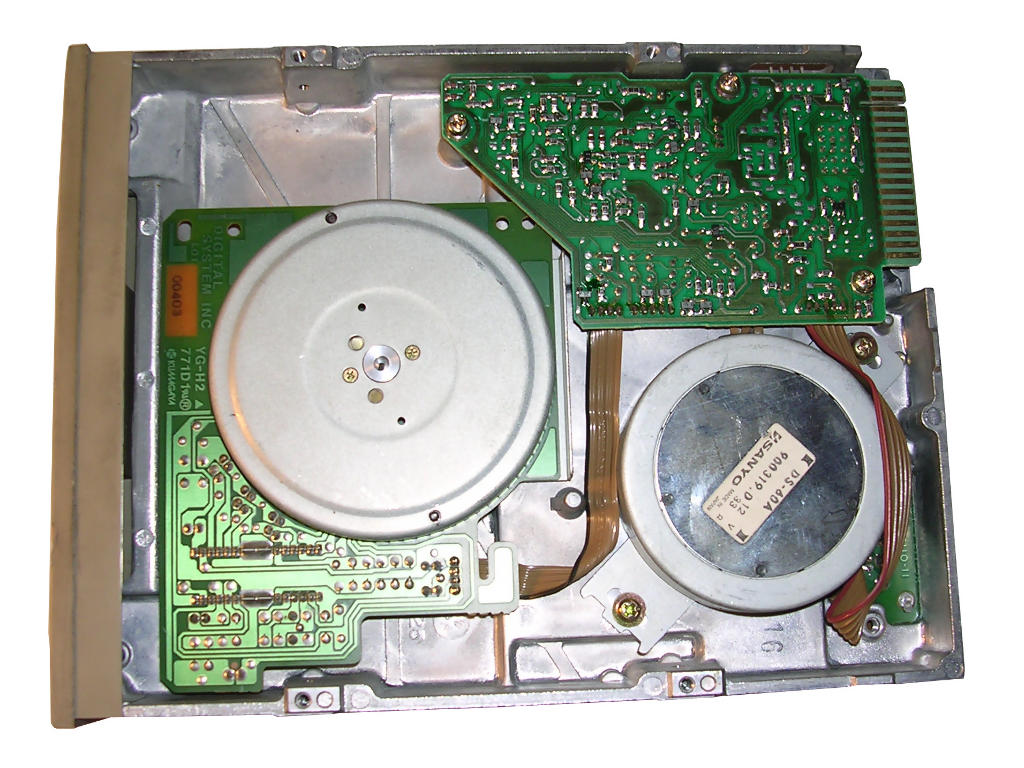
| Digital DS-53A | ||
| Density: Double (360K
in PC) Jumpers accessible by cut-out in metal shielding. Head assembly and whole upper part covered by piece of metal. Locking mechanism: Turning lever. Head moving mechanism: Stepper motor + metal belt, with shaft vertically (pic. below) Spinning mechanism: Motor in PCB.
|
 |
|
 |
 |
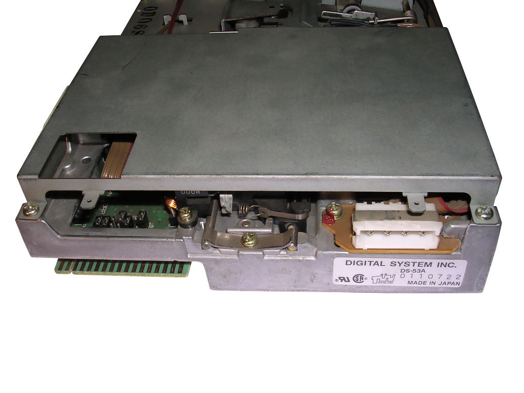 |
| General view | Electronics with SMD components | Rear |
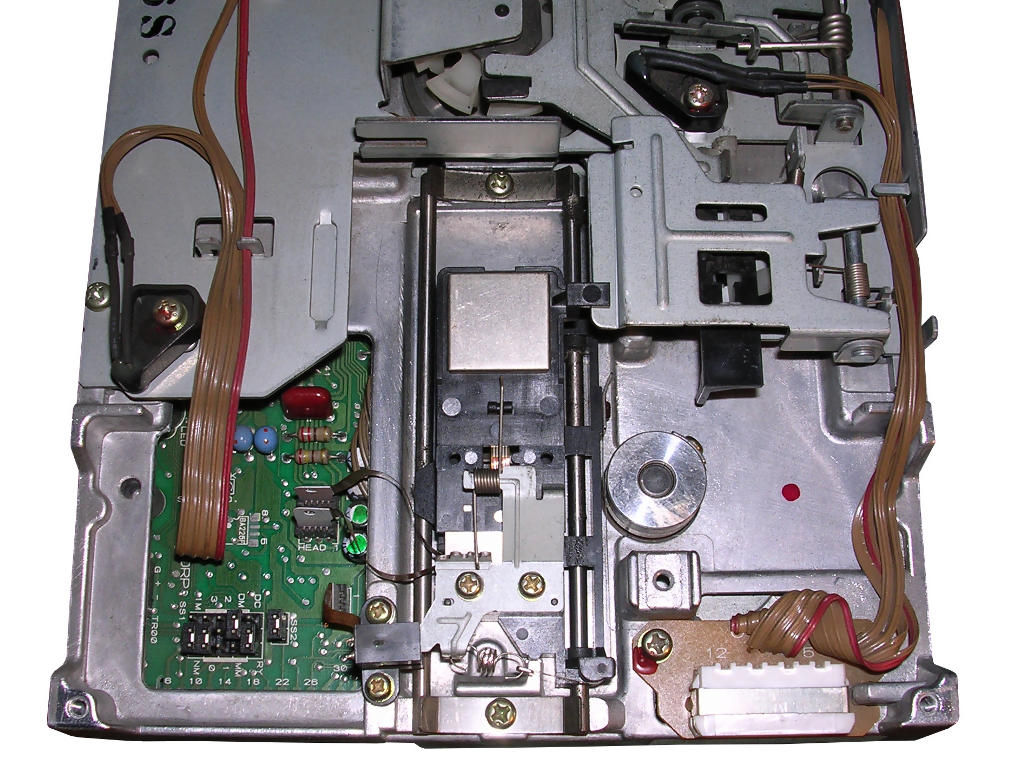
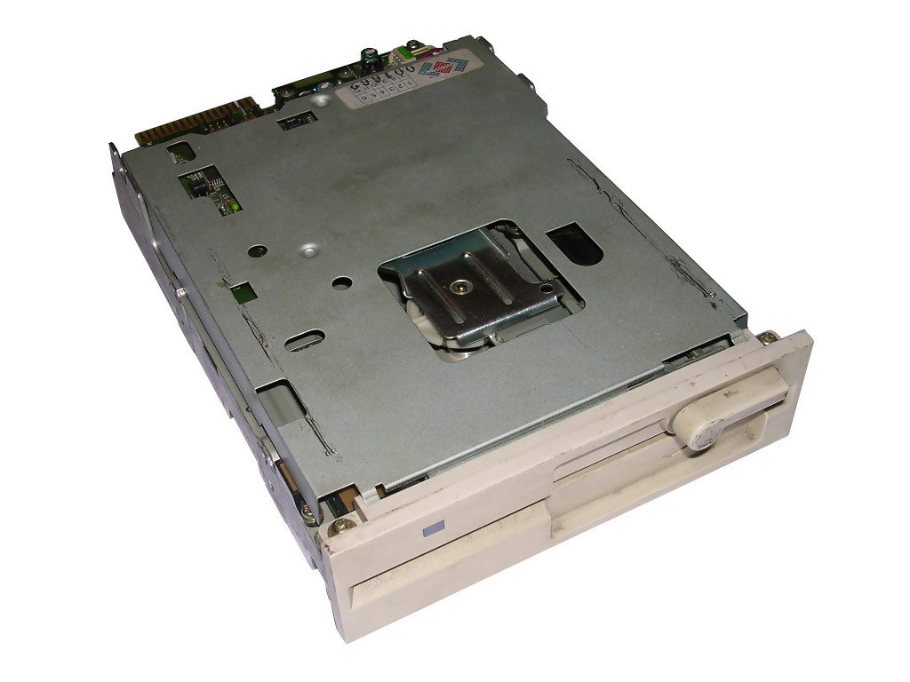
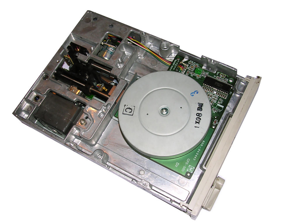
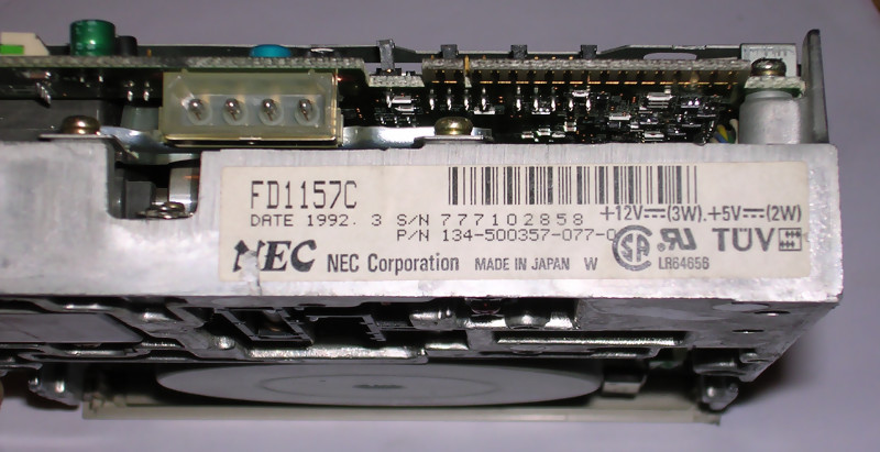
| NEC FD-1157C | |
| Density: High (1.2MB PC) Only simple jumpers. Head mechanism lifted and dropped by solenoid, it makes loud clicks which is normal. Upper assembly covered by piece of metal. Upper head has its own metal protective cap, glued with piece of foam. This piece may fall apart letting protective cap fall to the mechanical part - check it before testing drive! Locking mechanism: Turning lever. Head moving mechanism: Stepper motor moving head carrier with metal belt, shaft located horizontally. Spinning mechanism: Motor in PCB. Technical parameters on NEC website. |
 |
 |
 |
| Notice the solenoid - metal cylinder with blue label near head carrier. | |
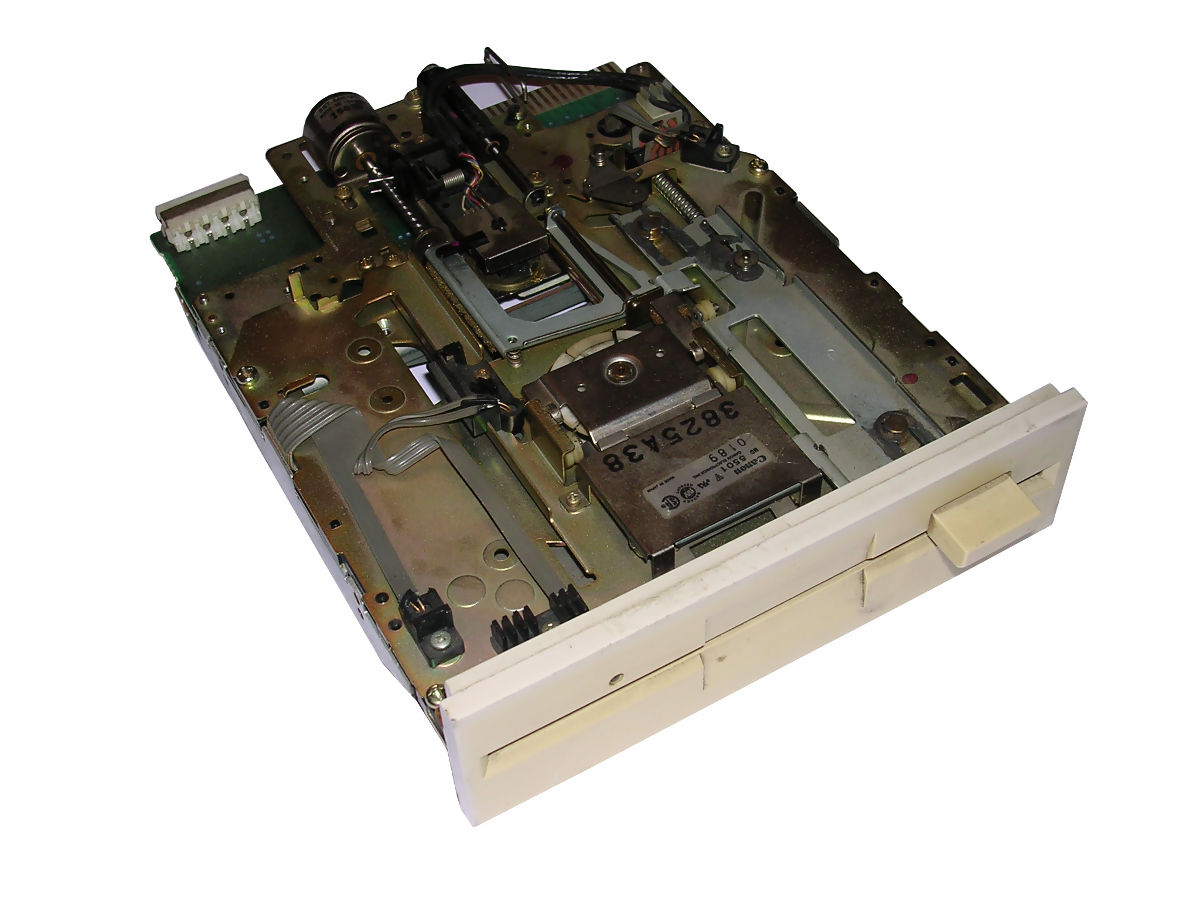
| Canon MD5501 | ||
| Density: High (1.2MB
PC) Only simple jumpers (DRIVE ID). Upper assembly should be covered by piece of metal, but it isn't in my unit. Drive was available with normal and low-profile panel to use in small computers. It's generally low-profile drive, it's half high as normal, making it 1/4 of standard full 5.25" height (full height is 2 typical drives). Locking mechanism: Button. Head moving mechanism: Stepper motor with worm screw shaft parallel to head moving direction. Spinning mechanism: Motor in PCB. If you really want to see the jumper settingsm look at this document. |
 |
|
 |
 |
|
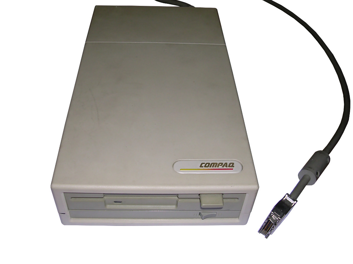
| Electronics is mainly in SMD, as the drive must be small. | Canon MD5501 with low-profile panel in case with AC power supply, as external FDD for Compaq laptop. | |
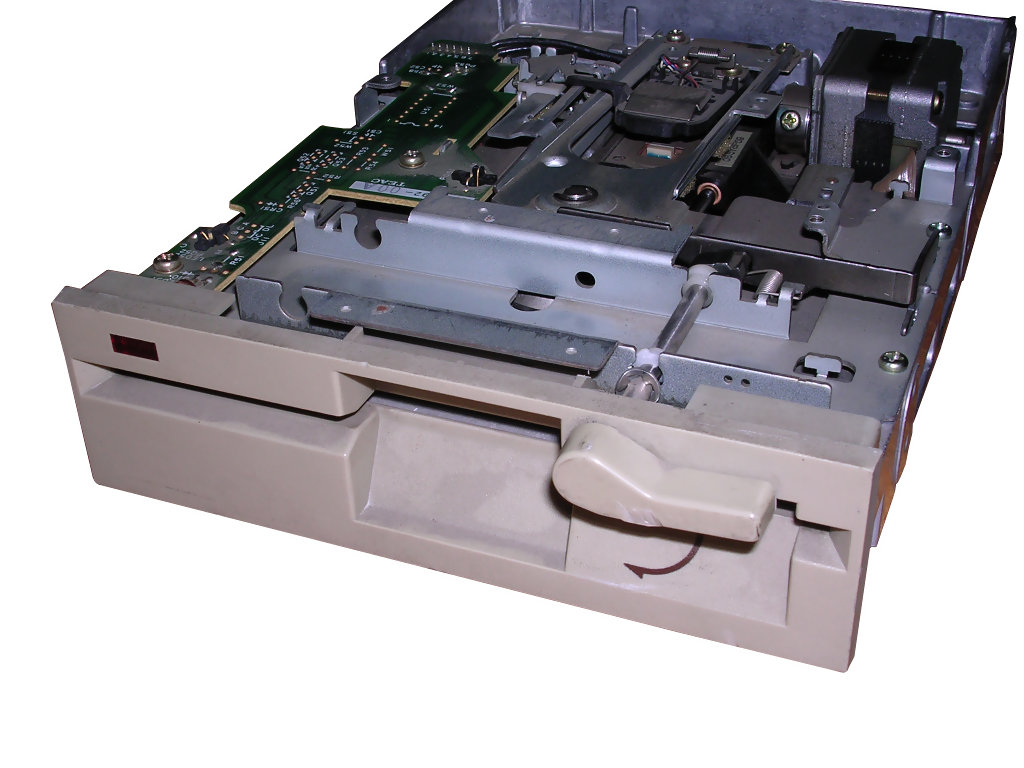
| TEAC FD-55GFR | ||
| Density: High (1.2MB
PC) Very popular drive manufactured with different front panels, LED colors and shapes. Jumpers as in TEAC drives - many soldered, many not. Manual can explain some of them. Upper assembly not protected by any metal shielding. Locking mechanism: Turning lever. Head moving mechanism: Stepper motor, metal belt, shaft horizonatlly. Spinning mechanism: Motor in PCB. |
 |
|
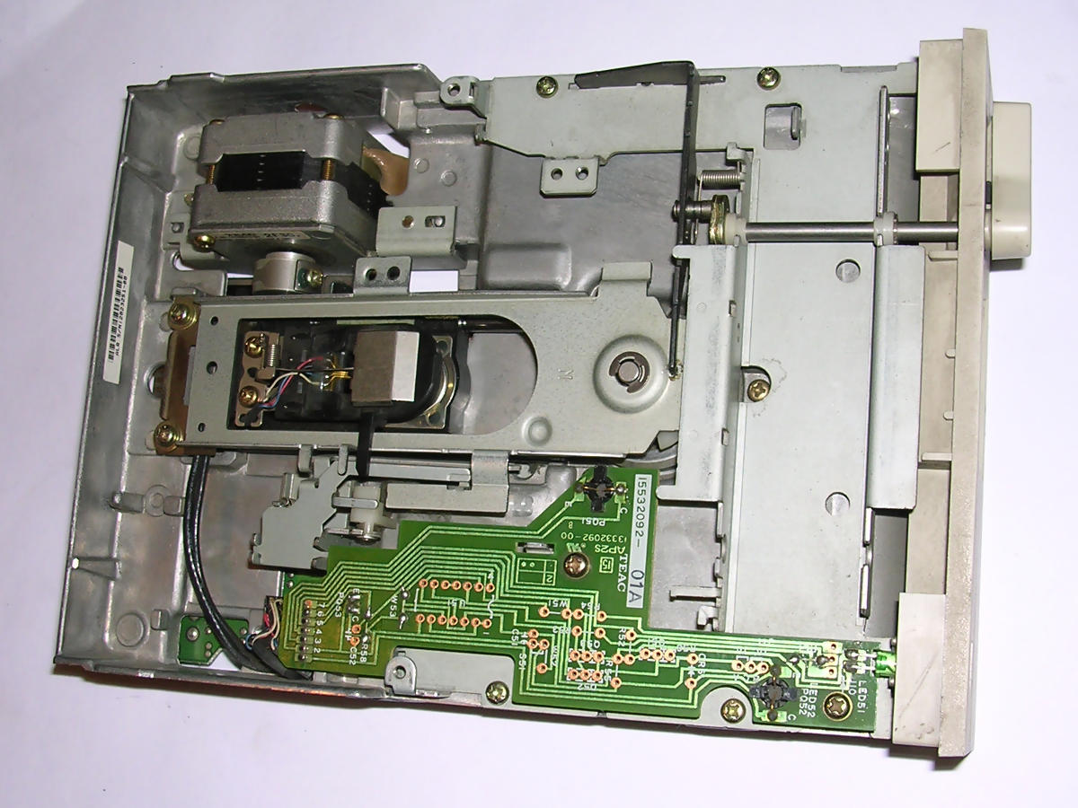 |
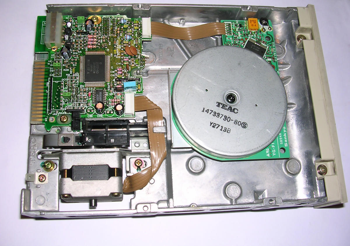 |
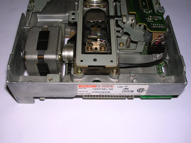 |
| Index hole electronics (?for hard-sectored disks?) not soldered. | Electronics PCB is very small. | |
 |
<- Exact view of front panel. | |
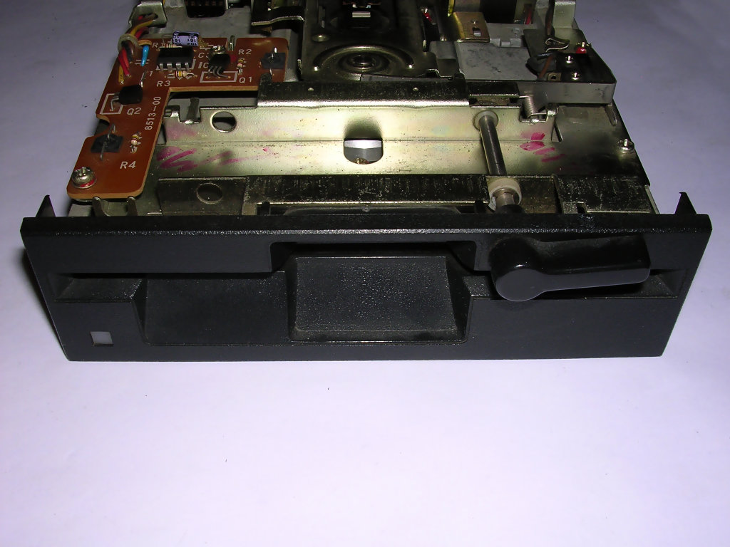
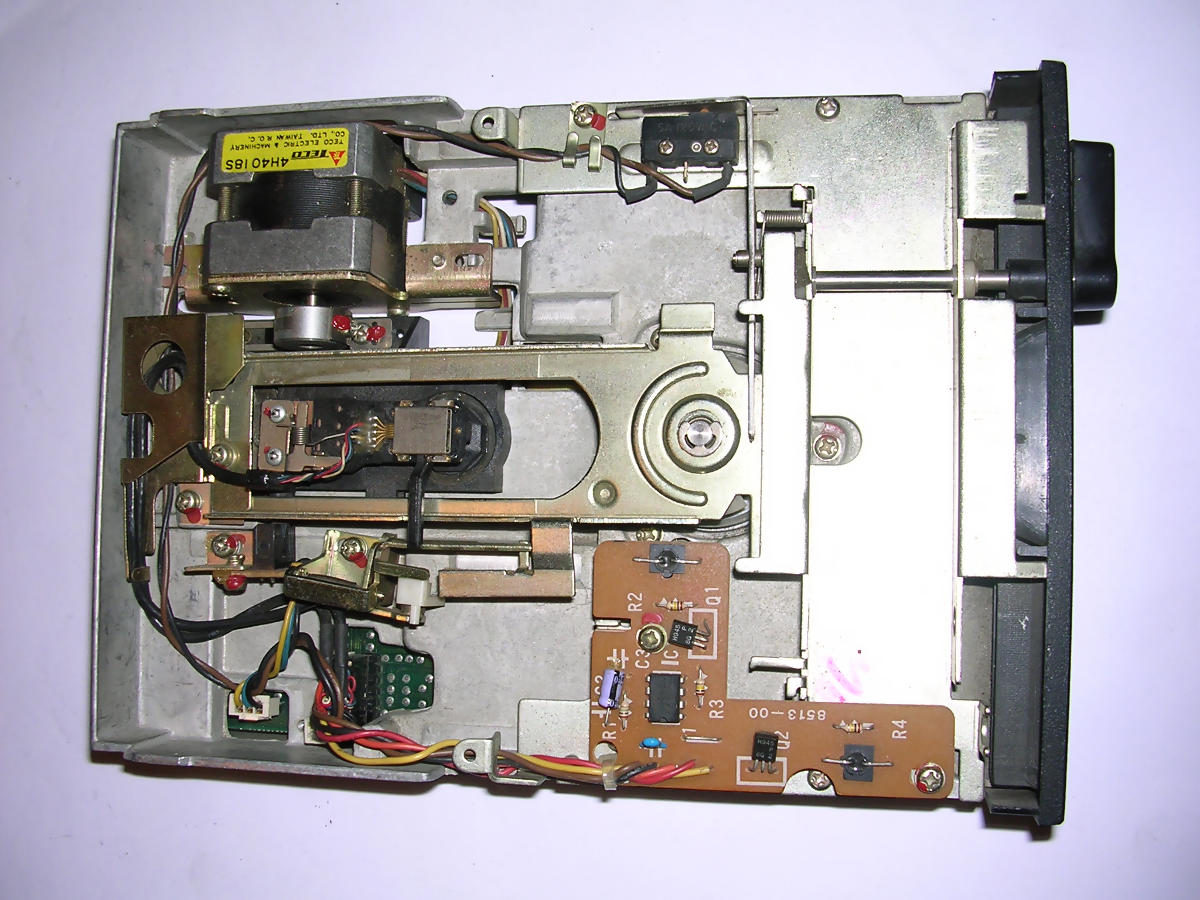
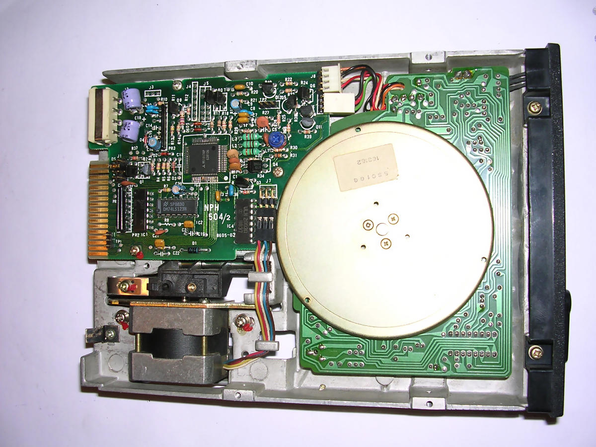
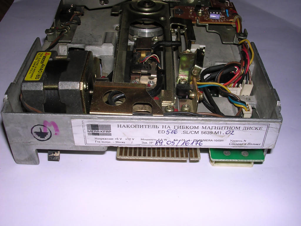
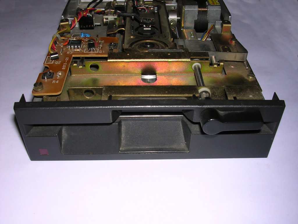
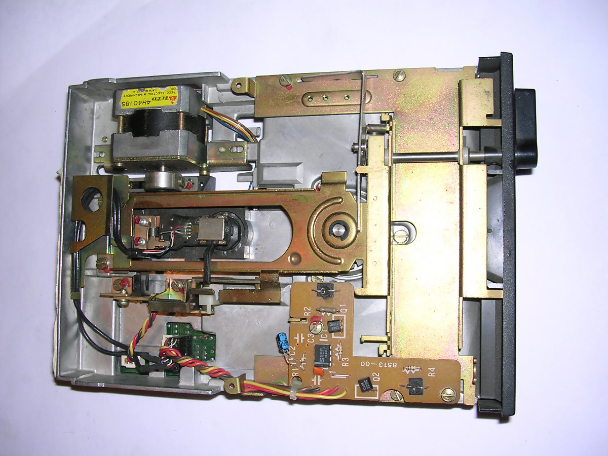
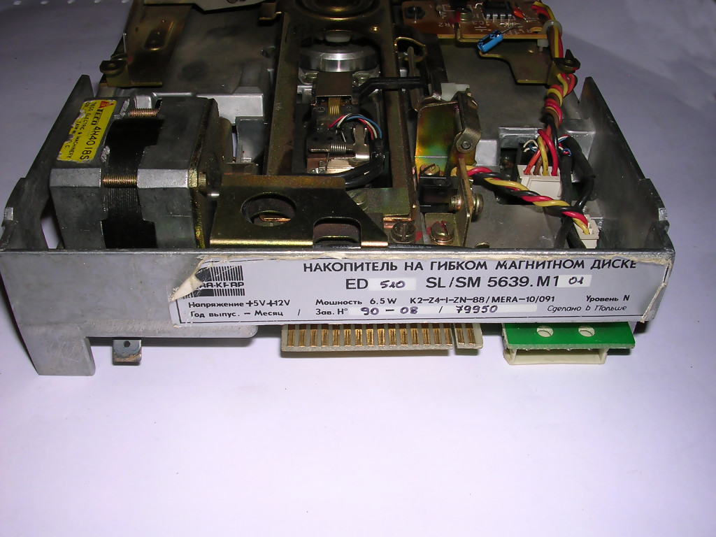
| Mera-KFAP ED-516 | ||||||
| Density: High (1.2MB
PC) Similar to early TEAC and Robotron products. Jumpers - mostly unknown. Built around western components, assembled in KFAP in Kraków, Poland. Notice two-color LED in front panel - it lighs red when 360K disks are used or green with 1.2MB disks. Locking mechanism: Turning lever. Head moving mechanism: Stepper motor, metal belt, shaft horizonatlly. Spinning mechanism: Motor in PCB.
|
 |
|||||
 |
 |
 |
||||
| Electronics is like in TEAC drives. | One SMD component, rest is through-hole | Export version has Russian description. | ||||
| Mera-KFAP ED-510 | ||||||
| Density: Double (360KB
PC or 720kB "Quad Density", not much supported in PC) Similar to early TEAC and Robotron products. Jumpers - mostly unknown. Built around western components, assembled in KFAP in Kraków, Poland. Red LED only. Locking mechanism: Turning lever. Head moving mechanism: Stepper motor, metal belt, shaft horizonatlly. Spinning mechanism: Motor in PCB.
|
 |
|||||
 |
 |
 |
||||
| Electronics similar to 516 model | Copare with electronics of 516. Some chips are missing, but board is the same. | Russian description, no CM (Unified System) number now. | ||||
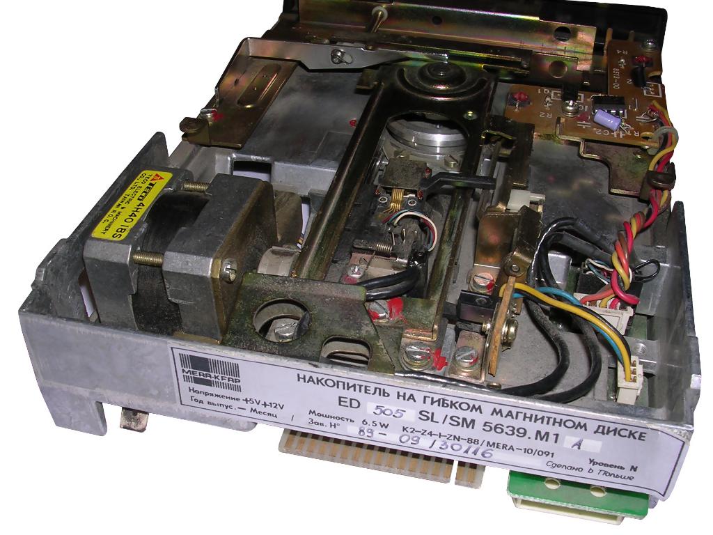
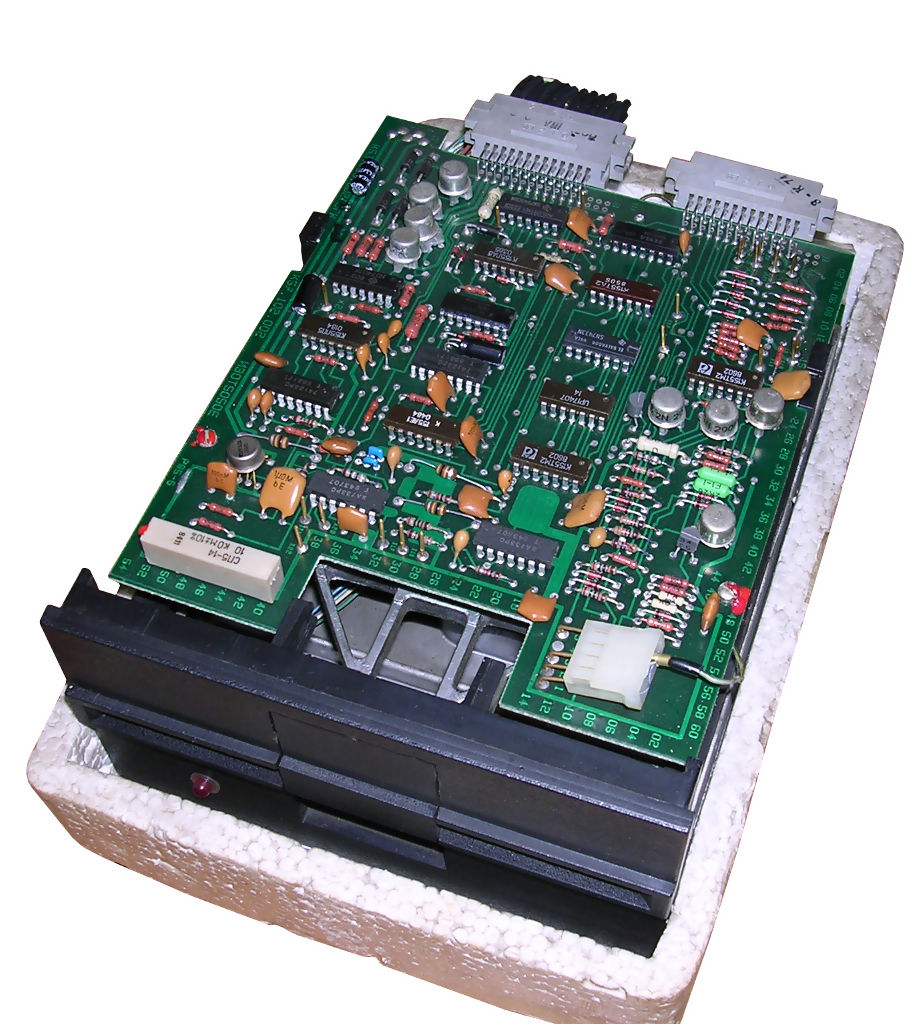
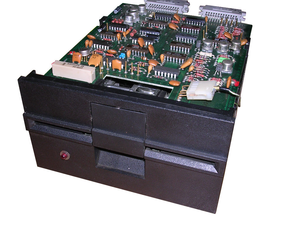
| Mera-KFAP ED-505 | ||||||
| Density: Double (360KB
PC) Similar to early TEAC and Robotron products, electronics is more robust than in later ED-510 model. Jumpers - mostly unknown. Built around western components, assembled in KFAP in Kraków, Poland. Red LED only. Locking mechanism: Turning lever. Head moving mechanism: Stepper motor, metal belt, shaft horizonatlly. Spinning mechanism: Motor in PCB. .
|
 |
|||||
 |
 |
 |
||||
| Upper part is not different than 510 | Compare with 510 - more through-hole chips, not SMD. | Russian description, but CM (SM) number in latin, not in cyrilic. | ||||
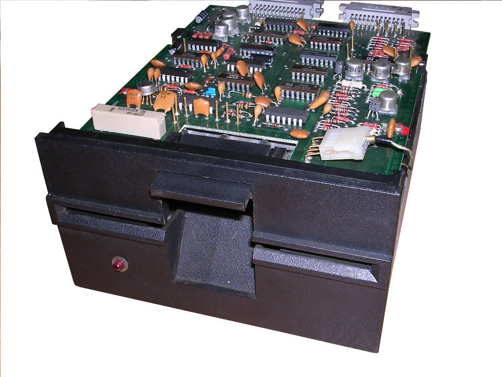
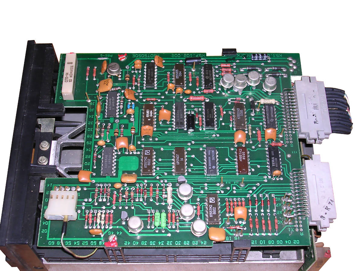
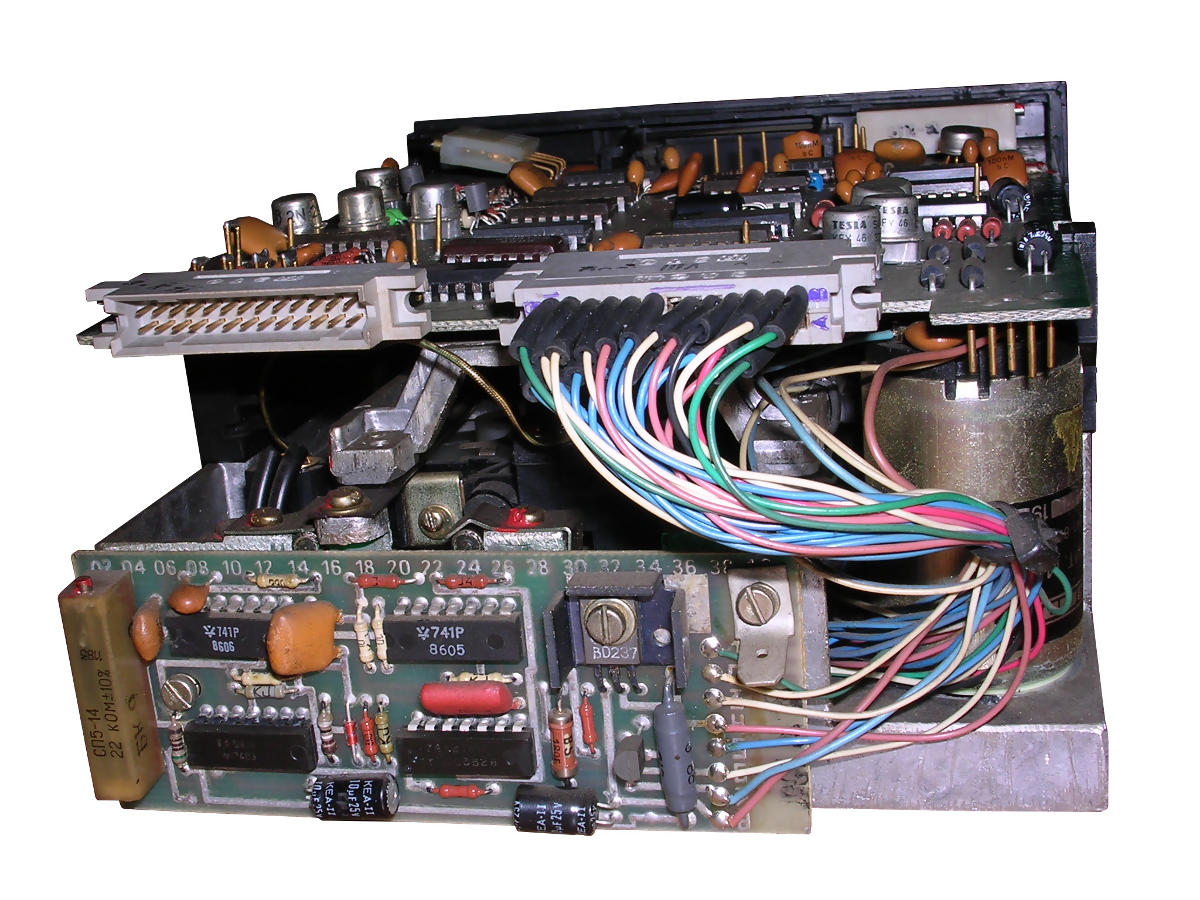
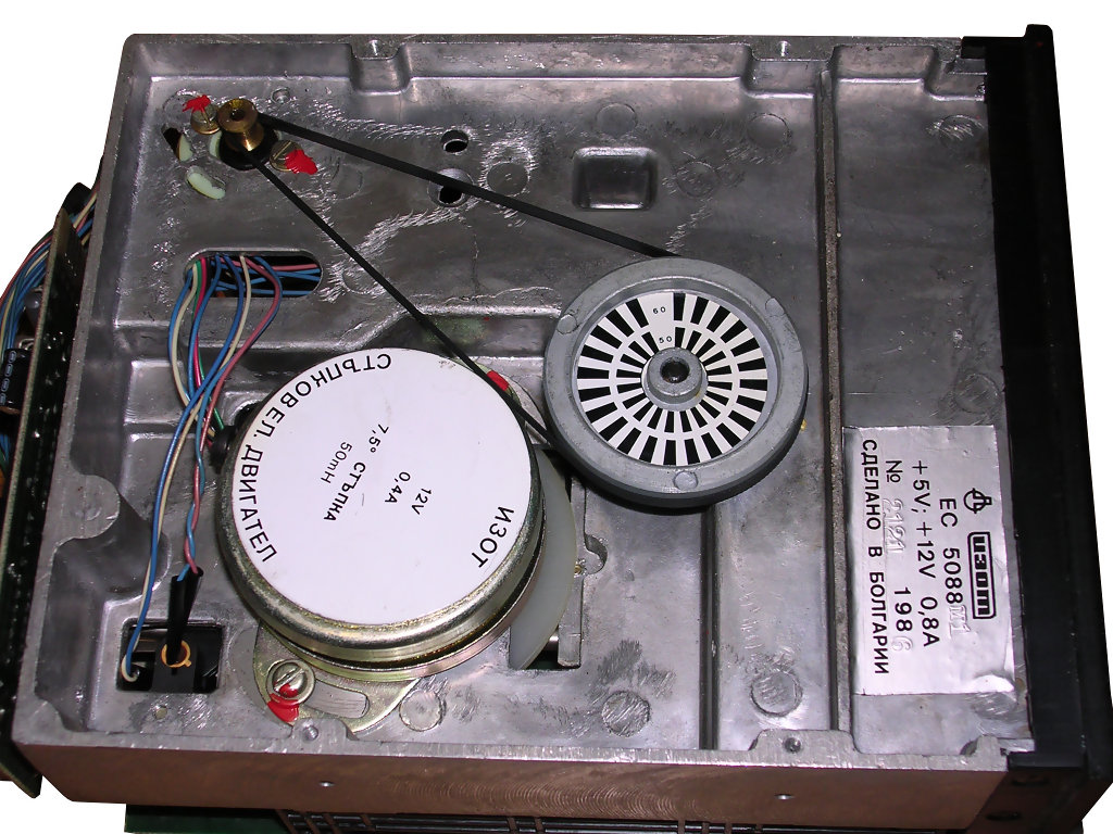
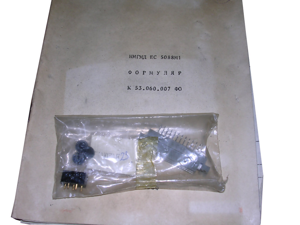
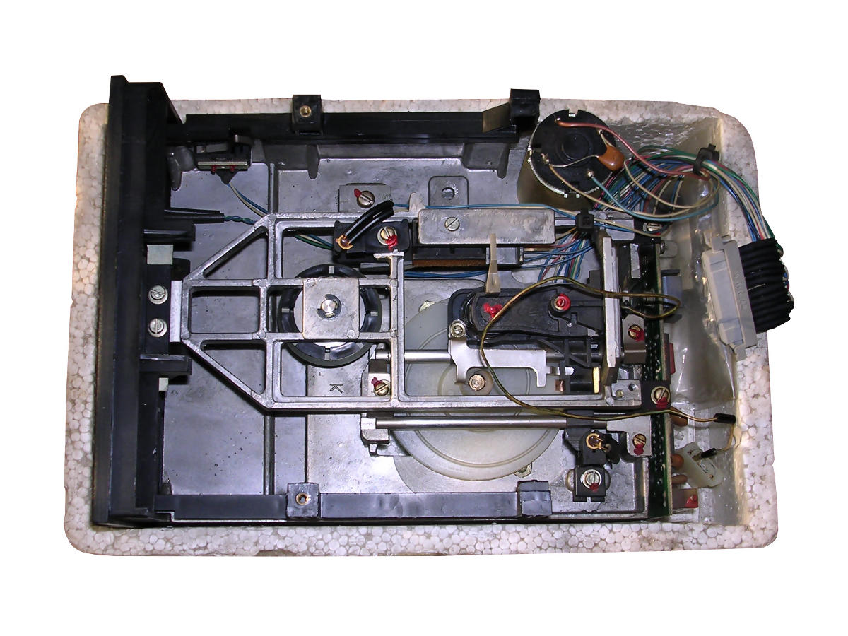
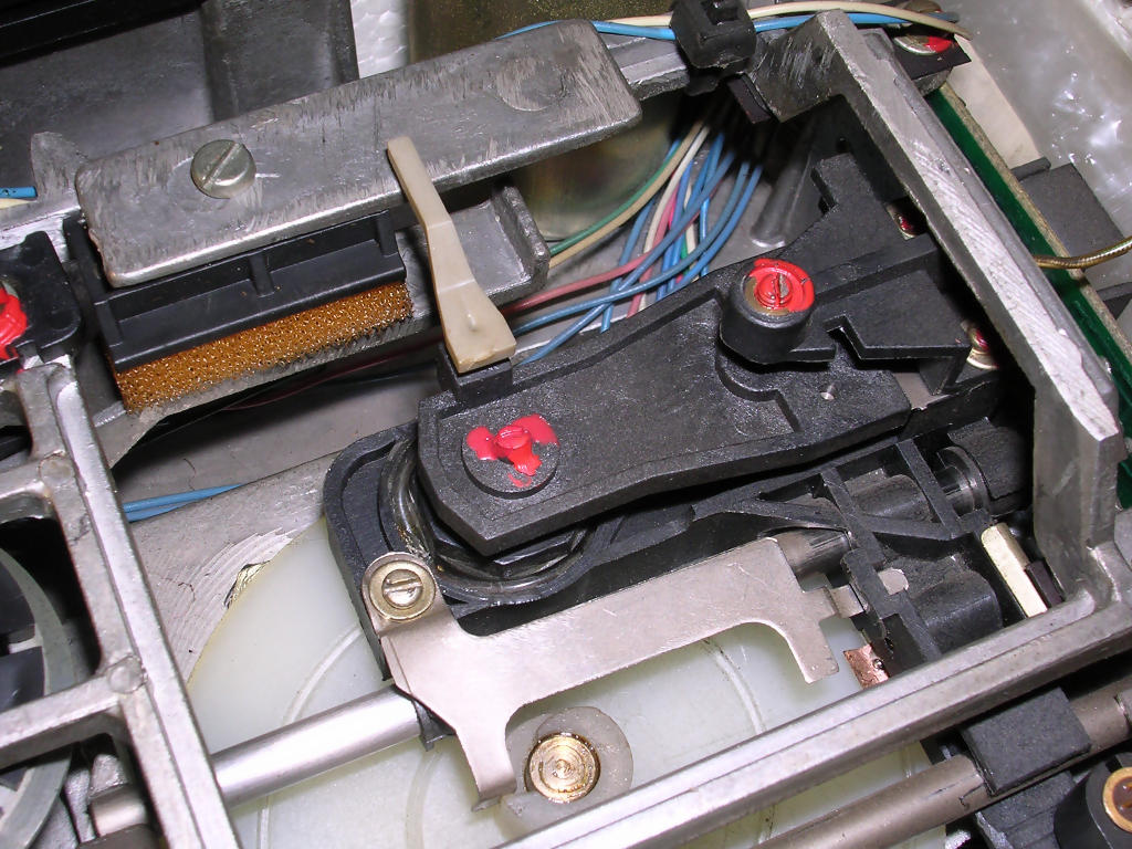
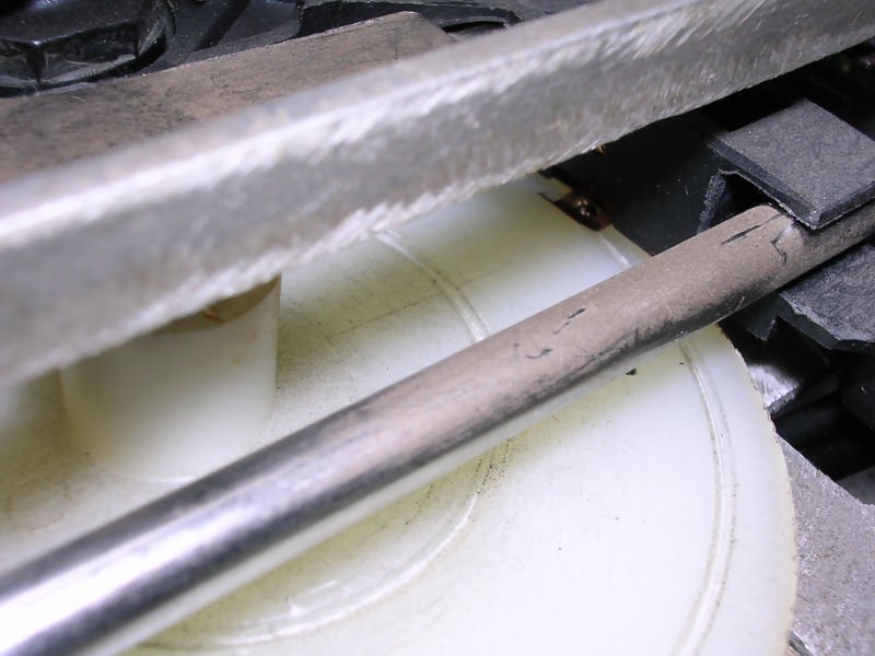
| IZOT EC5088 M1 | ||||
| Density: Low,
single-sided! Soviet Union computers were equipped with these. They were unreliable because worm screw was not deep enough. In Poland it was used in some Soviet measuring devices, in Soviet Union in Agat computers. Interface more or less compatible with typical one, but as in all Eastern block equipment connector and pinout is different. "M1" had 40 tracks, while "M" had 35. Made in Bulgaria. Locking mechanism: Flap. Head moving mechanism: Stepper motor, worm screw in a horizontally-placed disc. Spinning mechanism: Motor and typical belt transmission.
|
 |
|||
 |
 |
 |
||
| As it came to me | Flap closed | Flap opened | ||
 |
 |
 |
||
| Electronics with Soviet components | Motor driving electronics. | Bottom - belt transmission and head motor | ||
 |
 |
 |
||
| Manuals and connectors shipped with unit. | After removing electronics - visible head carrier assembly. | Details of head moving assembly. More detailed photo can be seen here. | ||
Some other drives:
 |
 |
 |
| BASF unit used in Commodore PC-10. Very quiet mechanics. | Another 360K BASF unit, with worm-screw disc head driving and strange locking mechanism. Works well in old PC. | |
 |
 |
|
| Drives in Siemens PC/X, one of first European PCs. | Floppy disks accessories and stuff. | |